Hydraulic energy recovery apparatus for working machine

a technology of working machine and energy recovery apparatus, which is applied in the direction of mechanical equipment, soil-shifting machines/dredgers, accumulator installations, etc., can solve the problems of performance degradation, the sealing gas pressure in the accumulator gradually reduces, and the effect of improving convenience and reliability

Active Publication Date: 2021-10-19
NIHON KENKI CO LTD
View PDF10 Cites 1 Cited by
  • Summary
  • Abstract
  • Description
  • Claims
  • Application Information

AI Technical Summary

Benefits of technology

[0011]As described above, according to the present invention, the degradation condition of the accumulator is determined based upon the elapse time elapsed or the number of operations since the initial use of the accumulator, or the estimation value of the sealed gas pressure. Thereby, it is possible to notify an operator of the result of the degradation determination before actually broken or prompt the operator for the replacement of the accumulator as needed, thus improving convenience and reliability as the hydraulic energy recovery apparatus.

Problems solved by technology

Incidentally, in the hydraulic energy recovery apparatus according to the conventional technology, when the accumulator is broken or is remarkably lowered in performance, a fuel consumption amount suppression effect to be expected cannot be obtained.
Further, a pressurized gas sealed in a gas chamber of the accumulator is possibly leaked out to a hydraulic pipe arrangement.
Thereby, the sealed gas pressure in the accumulator gradually reduces, and in some cases, a so-called performance degradation occurs.
As a result, for example, as described in Patent Document 1, it is difficult to detect the performance degradation of the accumulator by a pressure detector provided in the hydraulic oil tank.
Further, even in a case where abnormality is detected after the accumulator is actually broken, the working machine such as a hydraulic excavator cannot work due to the break of the accumulator, thereby damaging the convenience.

Method used


Image

  • Hydraulic energy recovery apparatus for working machine
  • Hydraulic energy recovery apparatus for working machine
  • Hydraulic energy recovery apparatus for working machine

Examples


Embodiment Construction

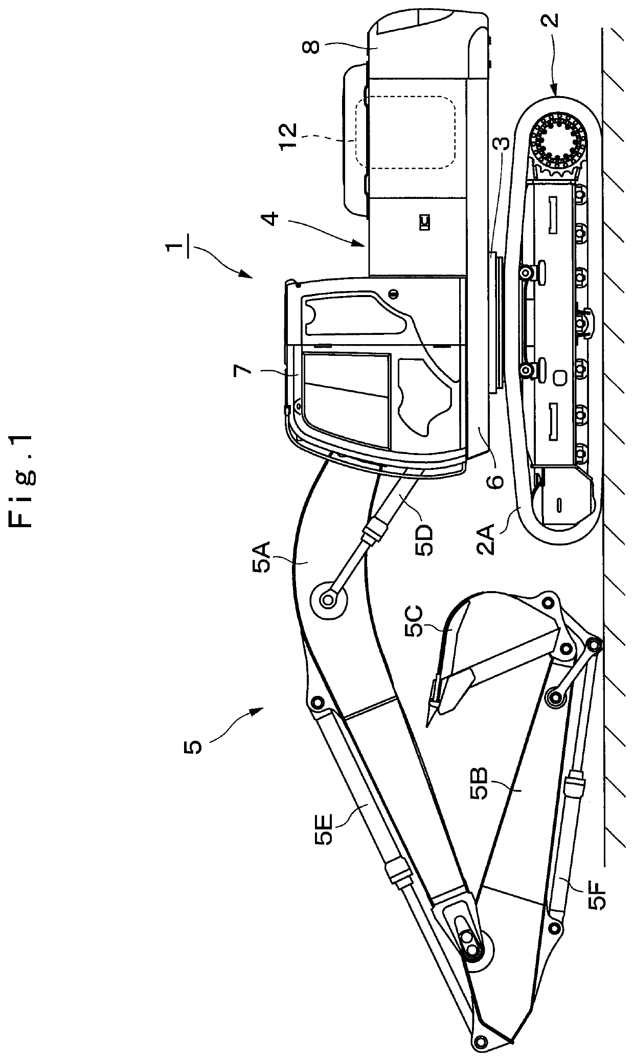
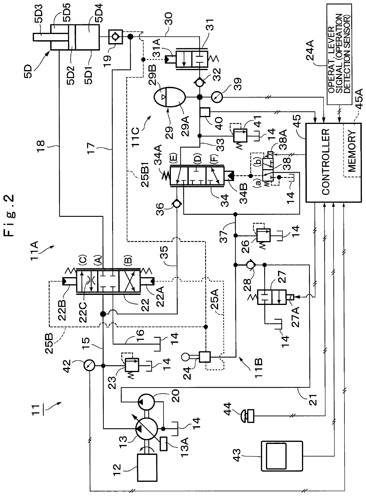
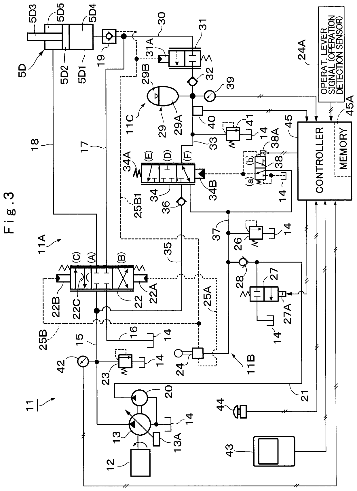
[0022]Hereinafter, an explanation will be in detail made of a hydraulic energy recovery apparatus for a working machine according to an embodiment of the present invention by taking a case of being applied to a hydraulic cylinder drive circuit to be mounted on a hydraulic excavator as an example with reference to FIG. 1 to FIG. 10 in the accompanying drawings.

[0023]In FIG. 1, a hydraulic excavator 1, which is a representative example of a working machine, is configured to include an automotive lower traveling structure 2 of a crawler type, a revolving device 3 mounted on the lower traveling structure 2, an upper revolving structure 4 rotatably mounted on the lower traveling structure 2 via the revolving device 3, and a working mechanism 5 with a multi-joint structure which is provided in the front side of the upper revolving structure 4 to perform an excavating work and the like. In this case, the lower traveling structure 2 and the upper revolving structure 4 form part of a vehicle...


PUM


Abstract

A controller (45) is provided with an elapse time measuring section (47A) that measures an elapse time (tx) elapsed since an initial use of an accumulator (29) based upon a reset signal from a reset switch (44), a number-of-operations measuring section (47B) that measures a number of operations of the accumulator (29), that is, a number (N) of boom lowering operations after a reset, based upon a detection signal from an accumulator side pressure sensor (39), a gas permeation amount estimating section (47C) that estimates an estimation gas permeation amount (Qloss) of the accumulator (29), a sealed gas pressure estimating section (47D) that finds an estimation sealed gas pressure (Pgs) of a gas chamber (29B) of the accumulator (29), and an accumulator degradation determining section (47E) that determines a degradation condition of the accumulator (29) and outputs the determination result.

Description

TECHNICAL FIELD[0001]The present invention relates to a hydraulic energy recovery apparatus for a working machine to be used for recovering energy of pressurized oil from a hydraulic actuator of a hydraulic excavator, for example.BACKGROUND ART[0002]In recent years, a working machine represented by a hydraulic excavator has been developed, which is provided with an accumulator on a hydraulic circuit for the purpose of a load reduction of a hydraulic pump or efficient reuse of hydraulic energy (Patent Documents 1, 2). Among them, a conventional technology of Patent Document 1 has the configuration that a branch oil path is provided in a main pipe for connection between a hydraulic actuator and a directional control valve to be connected to the accumulator. This accumulator accumulates high-pressure oil returning from the hydraulic actuator to a tank. At the full operation time of an operation lever, the pressurized oil in the accumulator is released to assist in an operation of the h...

Claims


Application Information

Patent Timeline
Patent Type & Authority Patents(United States)
IPC IPC(8): F15B1/08E02F9/22F15B21/14
CPCF15B1/08E02F9/2217F15B21/14F15B2201/51F15B2201/205F15B2201/3152F15B2201/31F15B2201/505F15B2211/20523F15B2211/20546F15B2211/212F15B2211/329F15B2211/30515F15B2211/6309F15B2211/6306F15B2211/6343F15B2211/6346F15B2211/6355F15B2211/67F15B2211/761F15B2211/8636F15B2211/865F15B2211/87F15B2211/88F15B19/005F15B1/024F15B1/033E02F9/267E02F9/226F15B1/02
Inventor TAKAHASHI, KIWAMUHIJIKATA, SEIJIHOSHINO, MASATOSHIOGAWA, YUICHIISHIKAWA, KOUJI
Owner NIHON KENKI CO LTD
Why Eureka
Try Eureka