
Eye surface topographer

a topographer and eye surface technology, applied in the field of optical systems, can solve the problems of less accurate measurement of placido disk topographers, limited measurement area of placido instruments, and inability to measure scleral surfaces with different optical properties, and achieve the effect of convenient focus and improved accuracy

Active Publication Date: 2021-10-26
EAGLET EYE BV
View PDF3 Cites 0 Cited by
  • Summary
  • Abstract
  • Description
  • Claims
  • Application Information

AI Technical Summary

Benefits of technology

[0021]To still further improve the spectral discrimination, it is possible to use blue diode lasers instead of the LED's.
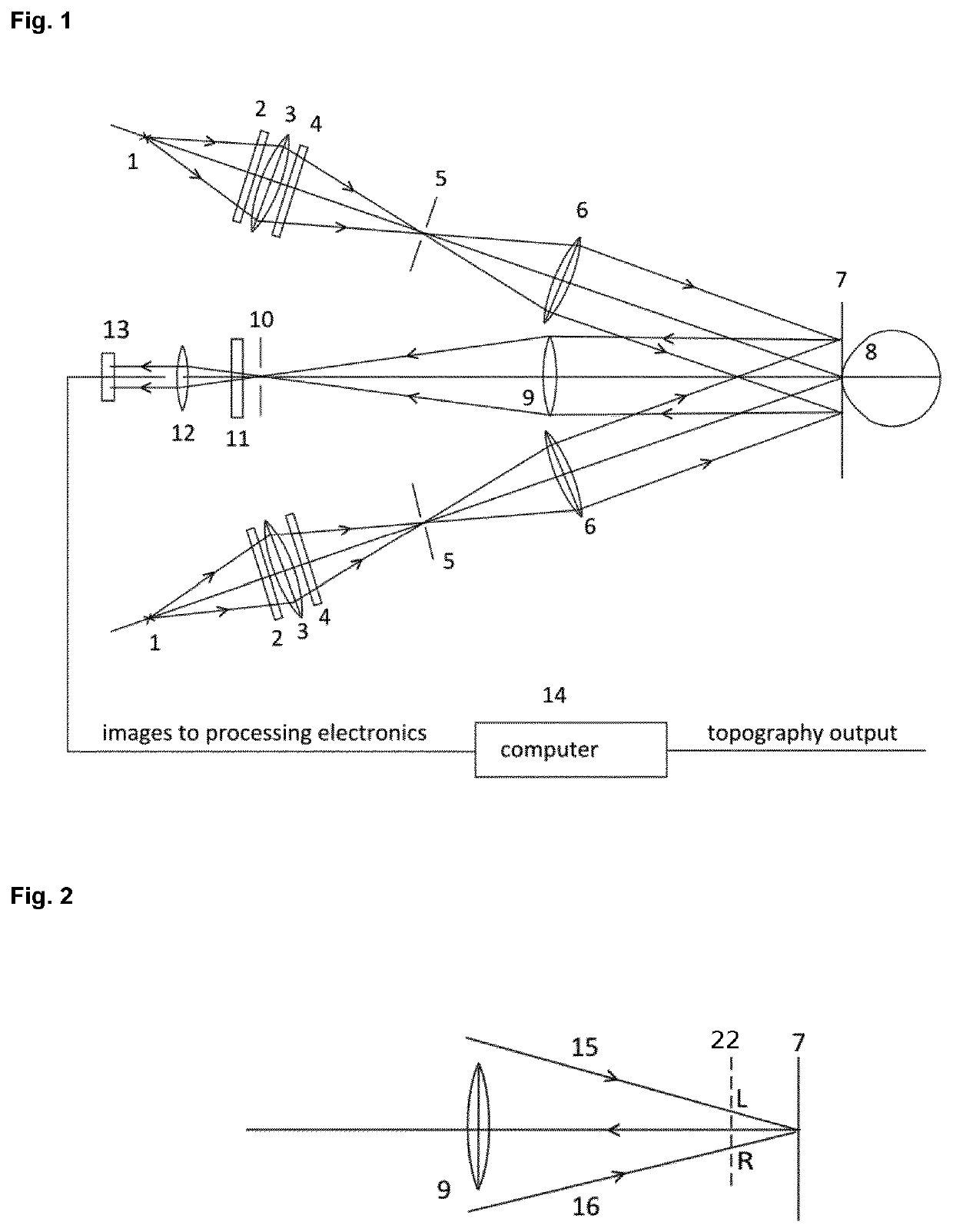
[0023]Another difference with the MST system is the presence of a focusing tool in the system. Said focusing tool comprises two narrow beams (15) and (16) focussed from different angles on the surface to be measured. Per reference to FIG. 2, using such narrow beams coming from the side and within the viewing branch of the front lens (9), an out-of-focus position is evident from sharp small and readily identifiable spots sideways from the central position. Being sharp and well delineated spots, focussing is made easy and achieved when these spots merge, i.e. when the distance between the spots is equal to zero.
[0024]In another embodiment of the present invention, the focus criterion is obtained in an automated manner by the computer software, making the focusing more accurate. Accurate focusing is important because higher order errors in the object-side telecentricity can lead to topography errors; when the focusing is more accurate (or when the defocus distance is known more accurately) it is possible to correct these topography errors by a software code.
[0027]The fringe patterns in a plane perpendicular to the camera optical axis must consist of straight lines and have a uniform period that is the same for both projections and independent of defocusing over a distance of, for example, 5 mm. This can be achieved by fine-tuning the magnification of the projection lenses (6), provided that the aberrations of these lenses are sufficiently well corrected. The fine-tuning is done by hand during the assembling of the system by small axial displacements of the lenses and measurement of the fringe period by computer software. Preferably, in the system according to the present invention the projection lenses (6) can be moved axially by actuators; in particular with the aid of computer calculations of the fringe images in the projected fringe images. In this manner, the telecentricity of the projection branches is improved.
[0037]Asymmetries of the cornea, mainly occurring along a horizontal cross-section (nasal to temporal) can be quantified accurately using EST. This is possible because of the extended measuring range of EST.
[0040]Both image capturing as well as image reconstruction are crucial for a veracious image reconstruction of the eye, for example in virtual reality applications, such as computer graphics. Therefore, in yet another embodiment, the EST system according to the present invention is for use in virtual reality applications, such as for example video games, film industry, training and simulation, or behavioural training. The presently available imaging technologies for capturing high-quality images of the eye are time consuming (45 minutes or more) and generally request a specific horizontal position of the test person, eventually including a horizontal fixation of the test person's head. With the present EST system, capturing of high-quality images of the eye can be performed in only a few minutes, thereby reducing the costs and increasing the comfort of the test person. Furthermore, the easy handling of the EST system allows the system to be used on a person, simply sitting or standing in an upright position, thereby additionally improving the comfort of the test person. Thus, in a further embodiment, the use of the system according to the present invention in virtual reality applications is disclosed.

Problems solved by technology

When the corneal surface is not spherical, however, the measurement by the Placido disk topographer is less accurate.
Moreover the measurement area of the Placido instrument is limited to the cornea because of its reflective properties.
Measurement of the scleral surface, that has more different optical properties, is not possible with the Placido topographer.
The MST promised a wide field (20 mm) height image of cornea as well as sclera, but due to insufficient computing power it was never introduced in the market.

Method used


Image

  • Eye surface topographer
  • Eye surface topographer

Examples


Embodiment Construction

[0050]The present invention aims to provide a new system for determining the topography of a diffusely reflecting curved surface. More in particular, the present invention relates to an optical system for determining the topography of the front surfaces, cornea and sclera of the human eye. Said optical system is also called the Eye Surface Topographer (EST). The system according to the present invention is here further described in detail based on the presented figures.

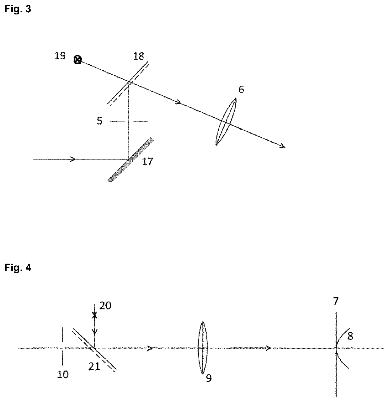
[0051]FIG. 1 shows an outline of the EST system in its most elementary form. The following components of the EST topographer system can be seen in FIG. 1: (1) is the projection source, which is a semiconductor diode, and thus can be a LED or a blue diode laser, the central wavelength of which is, for example, smaller than 500 nm; the spectral filter (2) blocks all radiation with wavelengths above, for example, 500 nm; the condensor lens (3) projects an image of the source on the slit diaphragm (5); the component (4) i...


PUM


Abstract

The invention concerns a system for determining the topography of a diffusely reflecting curved surface, that comprises two telecentric projection branches that project fringe images of a Ronchi grating on the diffusely reflecting curved surface, and a viewing branch of which the optical system projects an image of the illuminated surface on its camera target, and comprises further a computer that receives the fringe images recorded by the camera target and calculates from these the topography of the anterior eye surfaces, in which system the projection sources are semiconductor diodes and the optical system of the viewing branch is two-sided telecentric.

Description

FIELD OF THE INVENTION[0001]The invention relates to an optical system for determining the topography of diffusely curved surfaces. In particular, the present invention relates to an optical system for determining the topography of the front surfaces, cornea and sclera, of the human eye. Said system consists of two fringe projectors that project line patterns on an eye and a camera system that makes images of these fringe patterns, from which images the topography of the front surfaces of the eye can be calculated using specialized software.BACKGROUND TO THE INVENTION[0002]Classical instruments for measuring parameters of the topography of the cornea are known as keratometers. A significant improvement of the classical keratometer gave rise to the Placido disk corneal topographer that could be used to map a significant portion of the cornea (9 mm horizontally and 7.5 mm vertically). Further improvements of the Placido disk topographer have led to an extension of the measured area to...

Claims


Application Information

Patent Timeline
Patent Type & Authority Patents(United States)
IPC IPC(8): A61B3/107A61B3/14G01B11/255G01B11/25
CPCA61B3/107A61B3/145G01B11/255G01B11/2536G01B11/25
Inventor KESSELS, HENRICUS M. M.BRASSÉ, JAN G. M.VELZEL, CHRISTIAAN H. F.
Owner EAGLET EYE BV
Learn More