Management device and power storage system

a technology of management device and power storage device, which is applied in the field of management device and power storage system, can solve the problems of increasing the burden on each of the storage batteries, and achieve the effect of suppressing the deterioration of the power storage device and suppressing the increase of the electric-current burden

Active Publication Date: 2021-10-26
PANASONIC INTELLECTUAL PROPERTY MANAGEMENT CO LTD
View PDF12 Cites 1 Cited by
  • Summary
  • Abstract
  • Description
  • Claims
  • Application Information

AI Technical Summary

Benefits of technology

[0012]The present invention addresses the above situations with an object of providing a technique that is applicable to a power storage system including a plurality of power storage devices interconnected in parallel and that suppresses an increase in an electric-current burden on the power storage devices but suppresses their deteriorations.
[0015]The present invention makes it possible to suppress an increase in an electric-current burden on a plurality of power storage devices interconnected in parallel in a power storage system but to suppress deteriorations of the power storage devices.

Problems solved by technology

In the above control technique by which one of a plurality of storage batteries interconnected in parallel halts its operation by turns, if a load connected to the storage batteries increases, the burden on each of the storage batteries may also increase.

Method used


Image

  • Management device and power storage system
  • Management device and power storage system
  • Management device and power storage system

Examples


Embodiment Construction

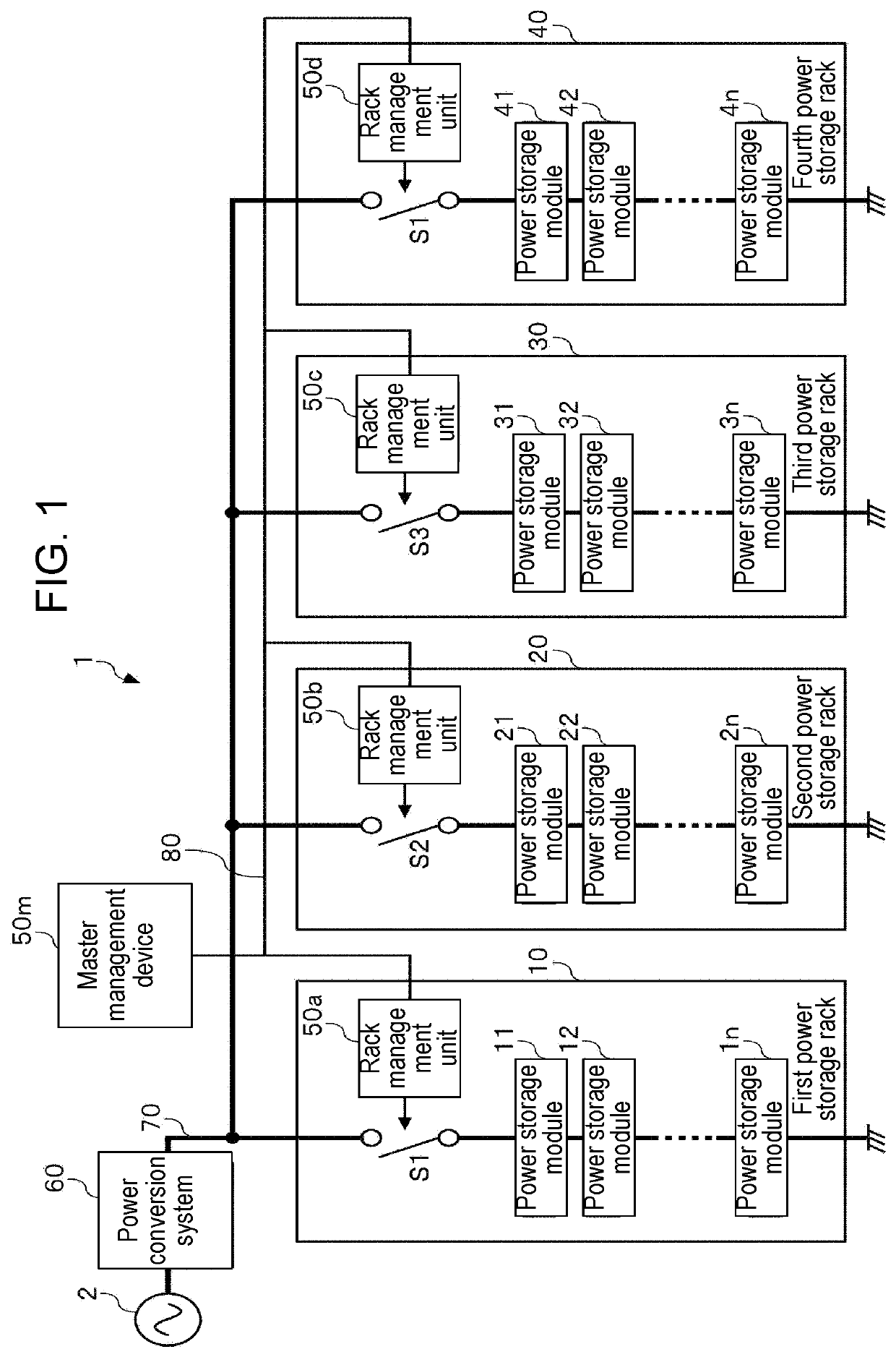
[0026]FIG. 1 is a view of a configuration of power storage system 1 according to an exemplary embodiment of the present invention. Power storage system 1 includes: a plurality of power storage racks 10 to 40 interconnected in parallel; and power conversion system 60. In the example of FIG. 1, four power storage racks (first power storage rack 10, second power storage rack 20, third power storage rack 30, and fourth power storage rack 40) are interconnected in parallel. Between the plurality of power storage racks 10 to 40 and power system 2 is power conversion system 60 connected.

[0027]Power conversion system 60 converts direct current (DC) power discharged from the plurality of power storage racks 10 to 40 into alternating current (AC) power and then outputs this AC power to power system 2. In addition, power conversion system 60 converts AC power received from power system 2 into DC power and then charges the plurality of power storage racks 10 to 40 interconnected in parallel wit...


PUM

PropertyMeasurementUnit
set time intervalaaaaaaaaaa
timeaaaaaaaaaa
accumulated timeaaaaaaaaaa

Abstract

A management device manages a plurality of power storage devices interconnected in parallel. In the management device, a halt controller halts an operation of at least one of the plurality of power storage devices during a period in which charged / discharged power between the plurality of power storage devices and a load is less than a set value. During the period in which the charged / discharged power is less than the set value, for example, the halt controller, by turns, halts an operation of one of the plurality of power storage devices at a set time interval.

Description

[0001]This application is a U.S. national stage application of the PCT International Application No. PCT / JP2017 / 001883 filed on Jan. 20, 2017, which claims the benefit of foreign priority of Japanese patent application 2016-017426 filed on Feb. 1, 2016, the contents all of which are incorporated herein by reference.TECHNICAL FIELD[0002]The present invention relates to a management device that manages power storage devices and to a power storage system.BACKGROUND ART[0003]For frequency regulation (FR) of commercial electric power systems (abbreviated below as power systems) which is made to stabilize their frequencies, power storage systems are now practically used. The trades of ancillary services using power storage systems have already started in the US market.[0004]Power systems provide stable frequencies by keeping the balance between their power demand and supply. However, some modern power systems are connected to many power generating systems using renewable energy, including...

Claims


Application Information

Patent Timeline
Patent Type & Authority Patents(United States)
IPC IPC(8): H01M10/44G01R31/392H02J7/02G01R31/3842H01M10/48H02J7/00G01R19/165H02J5/00H01M10/42
CPCH01M10/441G01R31/3842G01R31/392H01M10/48H01M10/482H02J7/0013H02J7/02G01R19/16542H01M10/4257H02J5/00Y02E60/10
Inventor YAMASAKI, JUNAGA, ETSUSHI
Owner PANASONIC INTELLECTUAL PROPERTY MANAGEMENT CO LTD
Why Eureka
Try Eureka