Connector and connector assembly for fixing connection terminals of different sizes
a technology of connecting connectors and connector assemblies, which is applied in the direction of coupling contact members, coupling device connections, securing/insulating coupling contact members, etc., can solve the problems of inconvenient use, inconvenient plugging, and easy bending or breaking of connection terminals, so as to reduce the internal temperature rise of the connector, safe and convenient use, and safe and convenient use
- Summary
- Abstract
- Description
- Claims
- Application Information
AI Technical Summary
Benefits of technology
Problems solved by technology
Method used
Image
Examples
embodiment 1
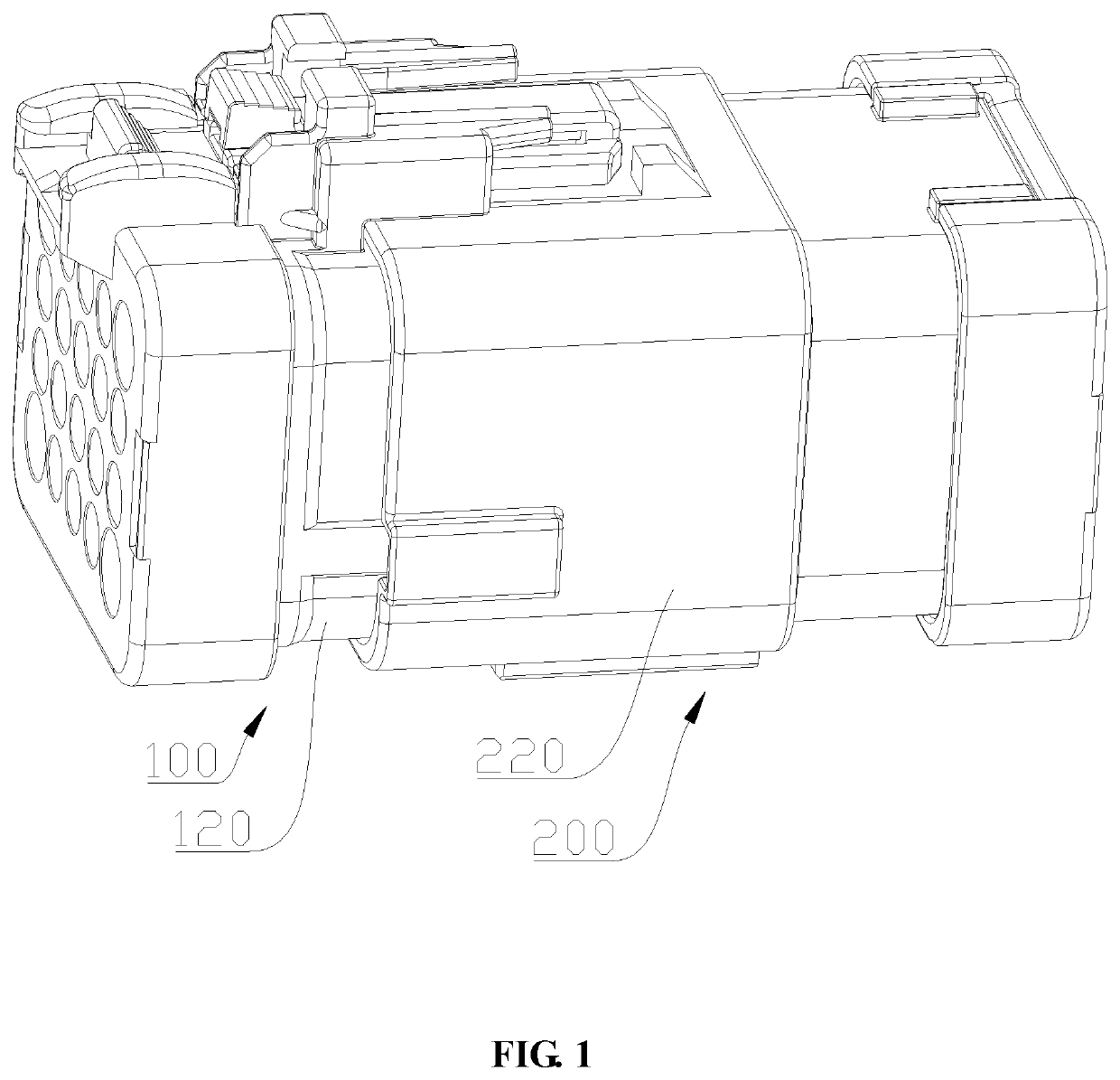
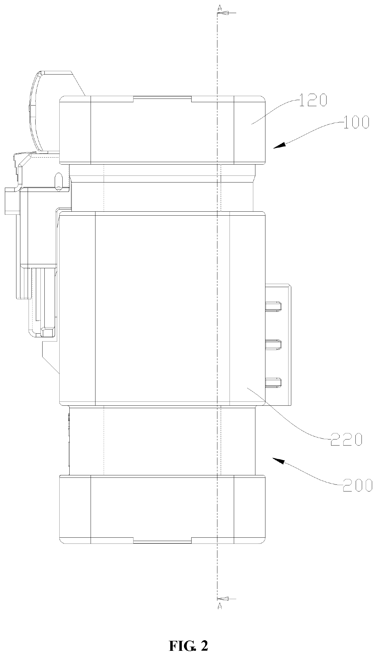
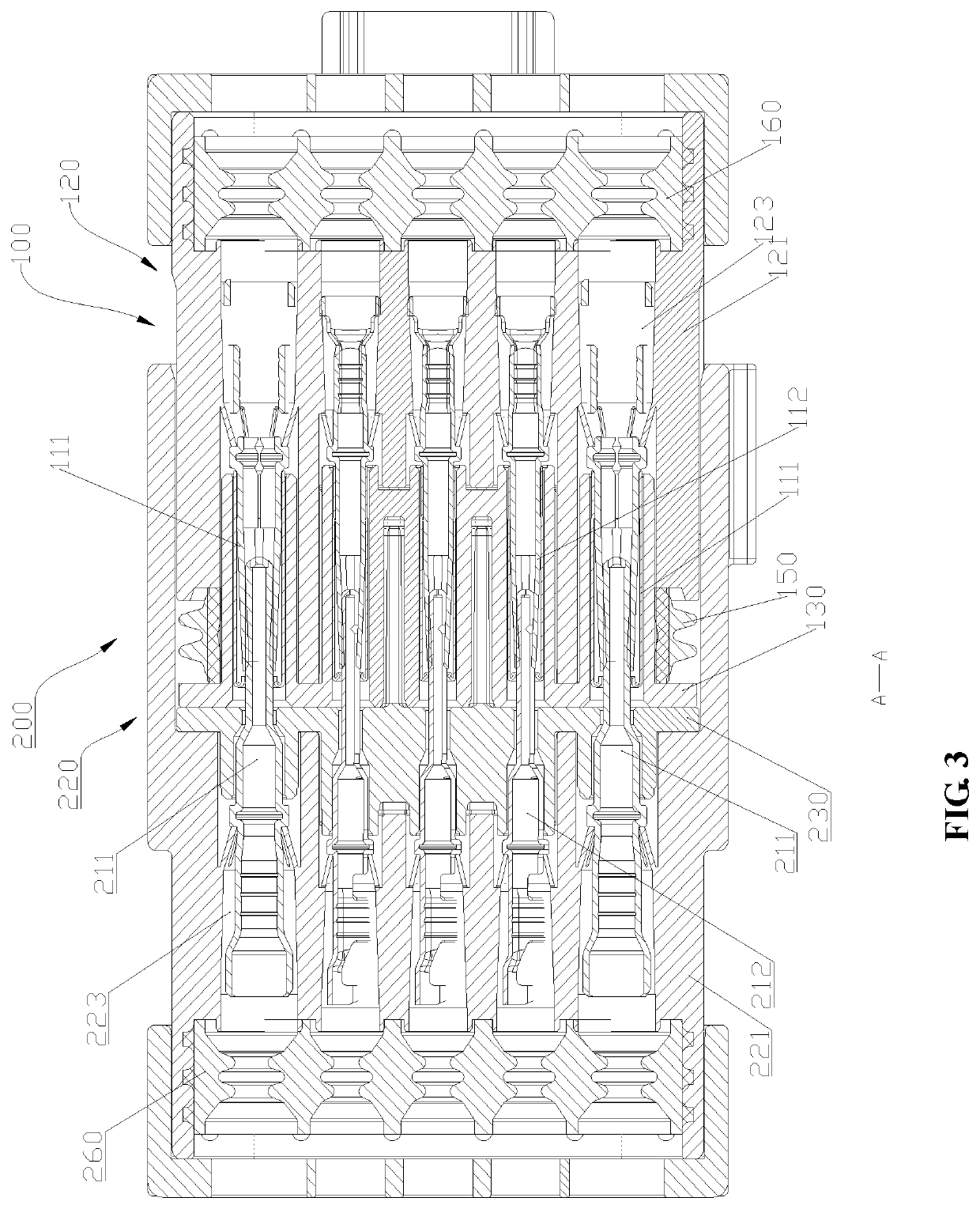
[0052]The mating connector assembly 100 shown in FIGS. 1-9 is configured for mounting a female terminal 110. The connector assembly 200 is configured for mounting a male terminal 210. The two connector assemblies are further described below.
[0053]The mating connector assembly 100 includes a mating connector 120 and a mating terminal retainer 130. The mating connector 120 has a mating housing 121 and a mating cavity 122. The mating housing 121 extends lengthwise for a selected length, and a desirable length and outer shape can be determined according to a circumstance of application. The mating housing 121 encloses the mating cavity 122. The mating connector 120 is configured for mounting a connection terminal, and in this embodiment, the connection terminal are illustrated as the female terminal 110. The female terminal 110 includes a first female terminal 111 and a second female terminal 112. A structure for mounting the female terminal 110 is provided in the mating cavity 122. The...
embodiment 2
[0065]As shown in FIGS. 10 to 16, the embodiment is another embodiment of the connector of the application, which is named as a connector assembly 200 for distinction from Embodiment 1. The structure includes a connector 220, a male terminal 210, and a retainer 230.
[0066]The connector 220 has a housing 221 and a cavity 222. The housing 221 extends lengthwise for a selected length, and a desirable length and outer shape can be determined according to a circumstance of application. The housing 221 encloses the cavity 222. The connector 220 is configured for mounting a connection terminal, and in this embodiment, the connection terminal are illustrated as the male terminal 210. The male terminal 210 includes a first male terminal 211 and a second male terminal 212. A structure for mounting the male terminal 210 is provided in the cavity 222. The structure may be a solid structure or another usable structure as long as it can fixedly mount the male terminal 210 in the housing 221. In th...
embodiment 3
[0081]FIG. 17 is a structural schematic view of another embodiment of the terminal retainer. In the example shown in FIG. 17, the terminal isolation plate 280 is structurally different from the terminal isolation plate 250 in Embodiment 2, and the plate body 231 is provided with only the first through-holes 232 which are all the same in size. In this embodiment, the terminal isolation plate 280 includes one vertical plate 261 and one transverse plate 262 which are disposed to intersect. The vertical plate 261 extends from an upper portion to a lower portion of the plate body 231 to isolate two adjacent rows of the second through-holes 233. The transverse plate 262 extends from a left portion to a right portion of the plate body 231 to isolate two adjacent upper and lower rows of the first through-holes 232.
[0082]The terminal isolation plate 280 further includes a short baffle 263 which is provided on both the vertical plate 261 and the transverse plate 262 and protrudes from the ver...
PUM
 Abstract
Description
Claims
Application Information
 - R&D
- Intellectual Property
- Life Sciences
- Materials
- Tech Scout
- Unparalleled Data Quality
- Higher Quality Content
- 60% Fewer Hallucinations
Browse by: Latest US Patents, China's latest patents, Technical Efficacy Thesaurus, Application Domain, Technology Topic, Popular Technical Reports.
© 2025 PatSnap. All rights reserved.Legal|Privacy policy|Modern Slavery Act Transparency Statement|Sitemap|About US| Contact US: help@patsnap.com


