Connector and connector assembly

a technology of connectors and connectors, applied in the direction of coupling contact members, coupling device connections, securing/insulating coupling contact members, etc., can solve the problems of inconvenient use, inconvenient plugging, and easy bending or breaking of the connection terminal, so as to reduce the internal temperature rise of the connector, safe and convenient use, and the effect of reducing the internal temperature ris

Active Publication Date: 2020-05-28
TYCO ELECTRONICS (SHANGHAI) CO LTD
View PDF0 Cites 0 Cited by
  • Summary
  • Abstract
  • Description
  • Claims
  • Application Information

AI Technical Summary

Benefits of technology

[0031]Compared with prior art, in the connector assembly provided by the application, the first through-holes are arranged around the second through-holes, so that the connection terminals having larger sizes for larger current therethrough can be disposed at the surrounding and be farther away from each other to help reduce the internal temperature rise of the connector thereby to be safe and convenient for use. The provision of the terminal retainer can help the connection terminal to be stable and firm. During plugging in, the terminal retainer can prevent the connection terminal from being bent or broken under stress, so that it is safe and convenient to use. The terminal retainer is provided with a bushing, so that the connection terminals can be isolated from each other to avoid mutual interference. The arrangement of the retaining block may enhance the firmness of the terminal retainer, and enable the connection terminal to be more stable and safer to use. The arrangement of the terminal isolation plate enables the terminal retainer to be more suitable for mounting the male terminal; the bushing and the isolation plate are separately provided on two surfaces of the plate body, and therefore the male terminals on either side of the plate body can be isolated or protected. Different heights of the bushings may enable the ends of the connection terminals to be axially staggered, so that during plugging in some of the male terminals firstly contact some of the female terminals, which requires a small force to plug in. Compared with the situation in which all of the male terminals are in contact and plug-in connection with all of the female terminals simultaneously at the beginning, the application can reduce the initial force during plugging in. The terminal retainer is provided with a hook, so that the terminal retainer can be conveniently hooked up and connected with the mating structure in the connector cavity. The plate body is provided with a third through-hole disposed on one side of the hook, so that the hook can be disconnected from the mating structure through the third through-hole, and the terminal retainer can be conveniently disassembled.

Problems solved by technology

Therefore, the connection terminal is prone to being bent or broken when plugged with a larger force during the plugging-unplugging process.
Due to the suspending arrangement of the connection terminal without any protective structure, it is prone to damage in the plugging-unplugging process and inconvenient to use.
In the case of many connection terminals, a larger initial force is required to plug and unplug a plurality of male terminals and female terminals simultaneously, resulting in difficulty in plugging and inconvenience in use.

Method used


Image

  • Connector and connector assembly
  • Connector and connector assembly
  • Connector and connector assembly

Examples


embodiment 1

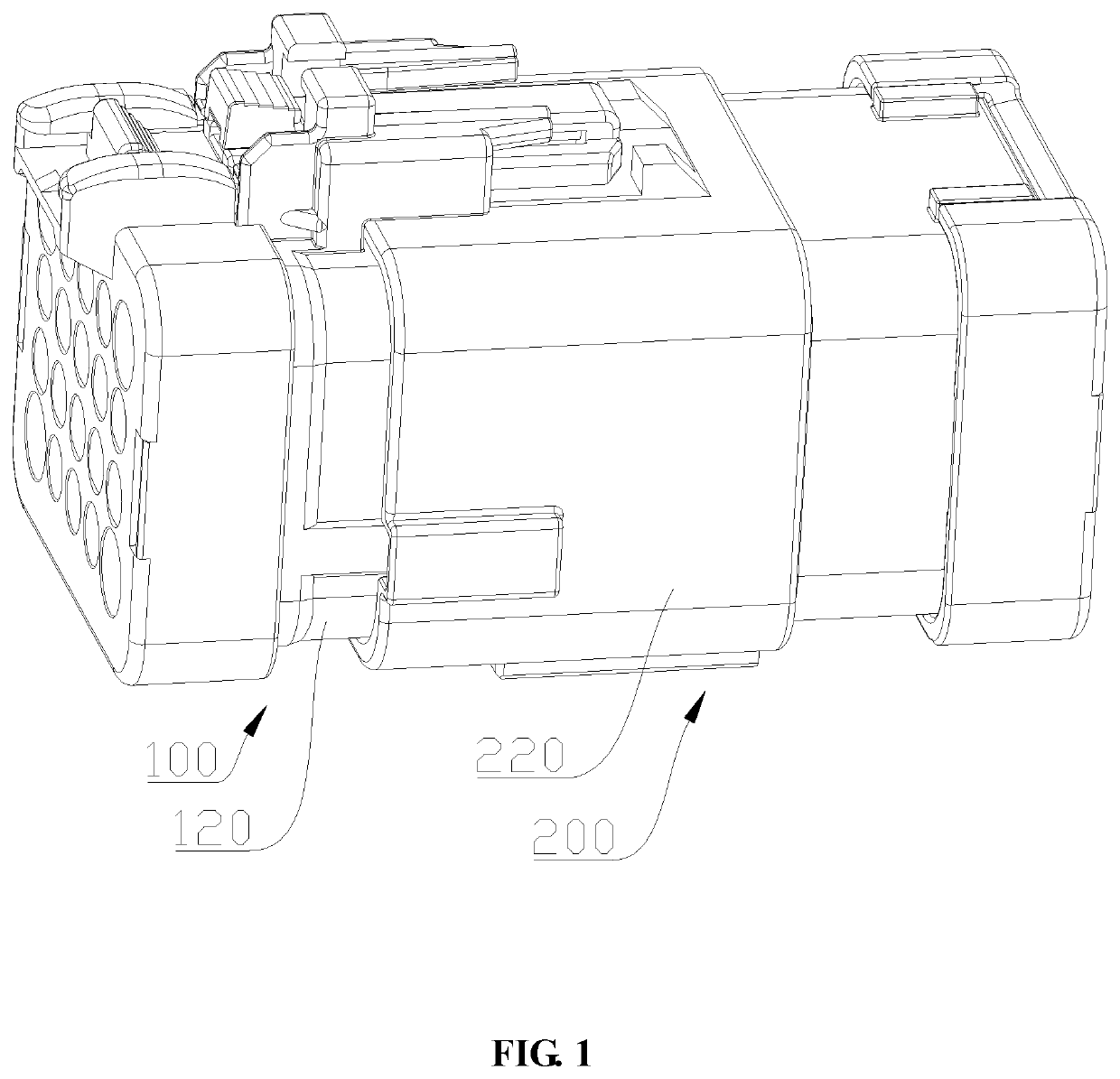
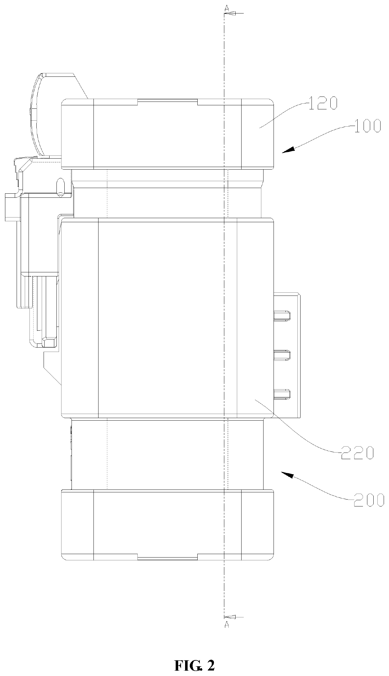
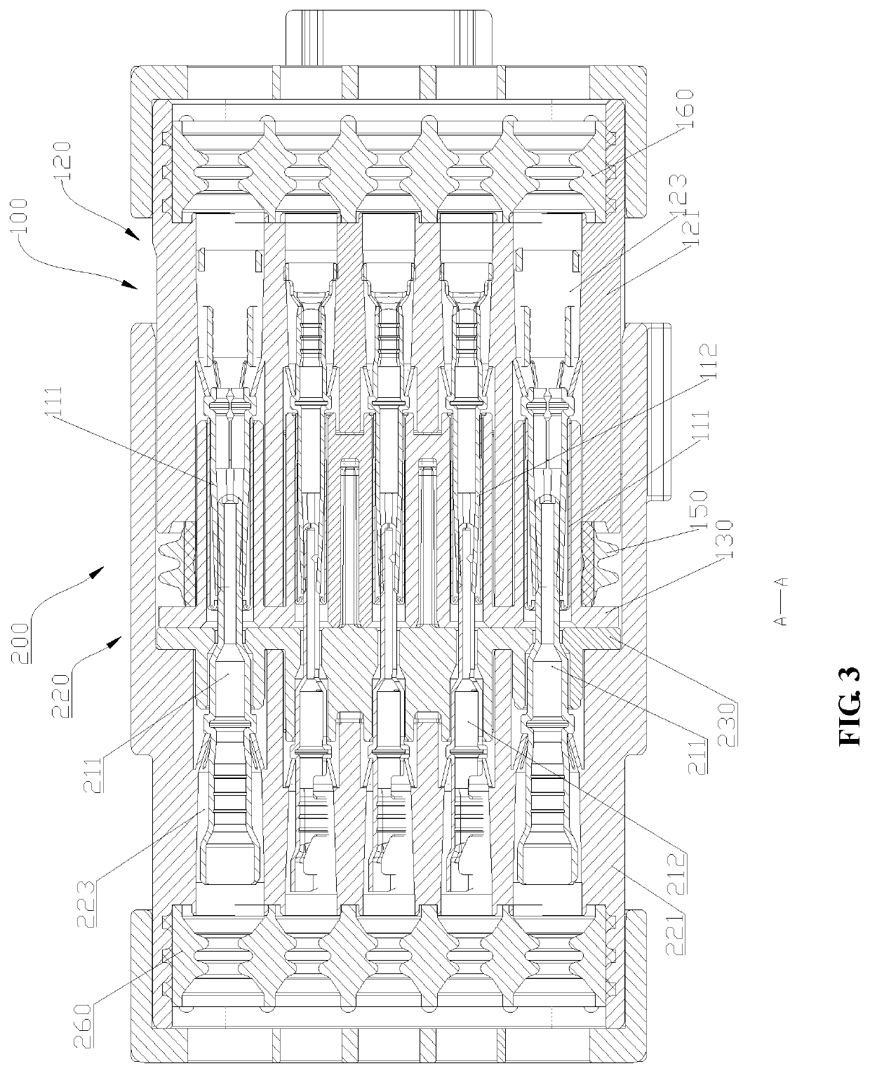
[0052]The mating connector assembly 100 shown in FIGS. 1-9 is configured for mounting a female terminal 110. The connector assembly 200 is configured for mounting a male terminal 210. The two connector assemblies are further described below.

[0053]The mating connector assembly 100 includes a mating connector 120 and a mating terminal retainer 130. The mating connector 120 has a mating housing 121 and a mating cavity 122. The mating housing 121 extends lengthwise for a selected length, and a desirable length and outer shape can be determined according to a circumstance of application. The mating housing 121 encloses the mating cavity 122. The mating connector 120 is configured for mounting a connection terminal, and in this embodiment, the connection terminal are illustrated as the female terminal 110. The female terminal 110 includes a first female terminal 111 and a second female terminal 112. A structure for mounting the female terminal 110 is provided in the mating cavity 122. The...

embodiment 2

[0065]As shown in FIGS. 10 to 16, the embodiment is another embodiment of the connector of the application, which is named as a connector assembly 200 for distinction from Embodiment 1. The structure includes a connector 220, a male terminal 210, and a retainer 230.

[0066]The connector 220 has a housing 221 and a cavity 222. The housing 221 extends lengthwise for a selected length, and a desirable length and outer shape can be determined according to a circumstance of application. The housing 221 encloses the cavity 222. The connector 220 is configured for mounting a connection terminal, and in this embodiment, the connection terminal are illustrated as the male terminal 210. The male terminal 210 includes a first male terminal 211 and a second male terminal 212. A structure for mounting the male terminal 210 is provided in the cavity 222. The structure may be a solid structure or another usable structure as long as it can fixedly mount the male terminal 210 in the housing 221. In th...

embodiment 3

[0081]FIG. 17 is a structural schematic view of another embodiment of the terminal retainer. In the example shown in FIG. 17, the terminal isolation plate 280 is structurally different from the terminal isolation plate 250 in Embodiment 2, and the plate body 231 is provided with only the first through-holes 232 which are all the same in size. In this embodiment, the terminal isolation plate 280 includes one vertical plate 261 and one transverse plate 262 which are disposed to intersect. The vertical plate 261 extends from an upper portion to a lower portion of the plate body 231 to isolate two adjacent rows of the second through-holes 233. The transverse plate 262 extends from a left portion to a right portion of the plate body 231 to isolate two adjacent upper and lower rows of the first through-holes 232.

[0082]The terminal isolation plate 280 further includes a short baffle 263 which is provided on both the vertical plate 261 and the transverse plate 262 and protrudes from the ver...


PUM


Abstract

The application discloses a connector and a connector assembly. The connector has a housing and a terminal retaining portion. The housing is provided with a cavity; the terminal retaining portion is disposed in the cavity and configured for fixing connection terminals; the terminal retaining portion is provided with a plurality of first mounting holes configured for accommodating first connection terminals and a plurality of second mounting holes configured for accommodating second connection terminals; the first mounting hole has a cross sectional size larger than that of the second mounting hole; the plurality of first mounting holes are disposed around all of the second mounting holes. Compared with prior art, in the connector assembly provided by the application, first through-holes are arranged around second through-holes, so that the connection terminals having larger sizes for larger current therethrough can be disposed at the surrounding and be farther away from each other to help reduce the internal temperature rise of the connector thus to be safe and convenient for use.

Description

TECHNICAL FIELD[0001]The application relates to a connector and a connector assembly.BACKGROUND ART[0002]Connectors are common components used for electrical connections. The connector is generally provided with a cavity in which a connection terminal is disposed, and the plug-in connection between two connectors enables a plug-in connection between a female terminal and a male terminal to achieve an electrical connection.[0003]In order to enable the connection terminals to be tightly plugged in and connected, it often requires a larger force to plug the male terminal and the female terminal in place. Therefore, the connection terminal is prone to being bent or broken when plugged with a larger force during the plugging-unplugging process. Due to the suspending arrangement of the connection terminal without any protective structure, it is prone to damage in the plugging-unplugging process and inconvenient to use. In the case of many connection terminals, a larger initial force is re...

Claims


Application Information

Patent Timeline
Patent Type & Authority Applications(United States)
IPC IPC(8): H01R13/42H01R13/627H01R13/629H01R13/52H01R13/514H01R24/20H01R13/05H01R25/00
CPCH01R13/514H01R13/6278H01R13/629H01R13/05H01R13/42H01R24/20H01R13/5202H01R25/00H01R13/5208H01R13/4364H01R13/6272H01R24/28
Inventor WAN, FENGYIN, HAOMAI
Owner TYCO ELECTRONICS (SHANGHAI) CO LTD
Why Eureka
Try Eureka