Energy saving type control method of composite switch and energy saving type composite switch

A composite switch, energy-saving control technology, applied in reactive power compensation, reactive power adjustment/elimination/compensation and other directions, can solve the problems of large heat generation of relay coils, waste of electric energy, and shortened service life of relays

Active Publication Date: 2012-06-20
NANNING MICRO CONTROL HIGH TECH
View PDF4 Cites 0 Cited by
  • Summary
  • Abstract
  • Description
  • Claims
  • Application Information

AI Technical Summary

Problems solved by technology

[0004] In addition, in the prior art, most of the coils of electromagnetic relays are directly connected to the power supply (or directly through series-connected control switches). Therefore, in the working state, the magnitude of the current passing through the coil before and after the contacts are pulled is consistent
Since the holding current of the relay coil used to maintain the contact pull-in after the c...

Method used


Image

  • Energy saving type control method of composite switch and energy saving type composite switch
  • Energy saving type control method of composite switch and energy saving type composite switch
  • Energy saving type control method of composite switch and energy saving type composite switch

Examples


Embodiment 1

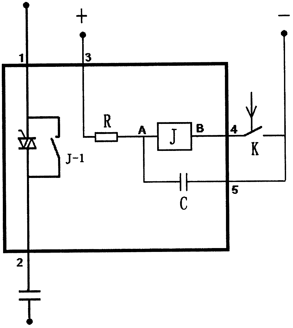
[0033] Figure 1 The energy-saving composite switch shown includes five external terminals: the first terminal 1 is used to connect to the power grid, the second terminal 2 is used to connect to the power capacitor, the third terminal 3 is used to connect the positive pole of the relay DC power supply, and the second terminal 3 is used to connect to the positive pole of the relay DC power supply. The four terminals 4 are connected in series with the relay control switch K to the negative pole of the relay DC power supply, and the fifth terminal 5 is directly connected to the negative pole of the relay DC power supply. The internal circuit connection relationship of the energy-saving composite switch is: between the first terminal 1 and the second terminal 2 is a parallel circuit of a bidirectional thyristor switch and a normally open contact of a relay; The output terminals of the silicon-controlled switching control circuit are connected; the third terminal and the fourth ter...

Embodiment 2

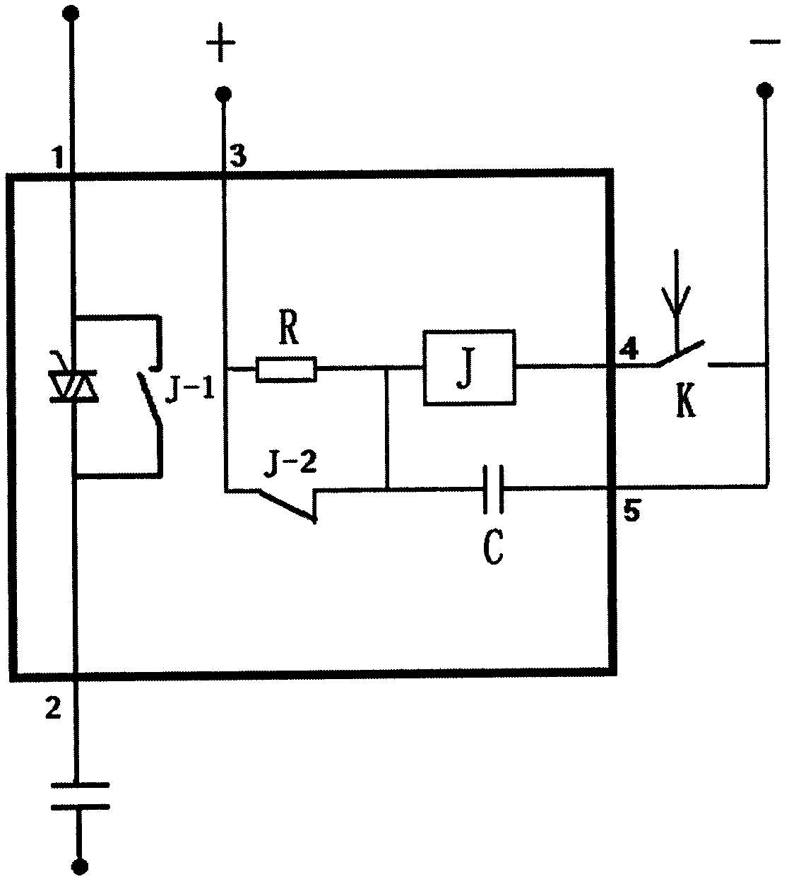
[0058] figure 2 It is a schematic diagram of the circuit principle of another embodiment of the energy-saving composite switch of the present invention. and figure 1 In comparison, the difference is that a pair of normally closed contacts of the relay are also connected in parallel at both ends of the resistor R.

Embodiment 3

[0060] refer to figure 1 , the compound switch energy-saving control method of the present invention is:

[0061] 1) Before the composite switch receives the power capacitor input command: the relay DC power supply in the composite switch charges the capacitor C through the resistor R;

[0062] 2) After the composite switch receives the input command of the power capacitor, it controls the thyristor in the composite switch to trigger conduction at the moment when the voltage crosses zero;

[0063] 3) After the power capacitor is put into stable operation, by controlling the closing of the switch K, the capacitor C is instantly discharged to the relay coil and the contacts of the relay are pulled in place;

[0064] 4) After the contacts of the relay are pulled in place, control the thyristor in the composite switch to be removed from the circuit;

[0065] During the stable operation of the power capacitor, the relay coil is connected in series with the resistor R to the DC po...


PUM

PropertyMeasurementUnit
Capacitanceaaaaaaaaaa

Abstract

The invention discloses an energy saving type control method of composite switch and an energy saving type composite switch. A first terminal of the composite switch is used for connecting with an electric network, a second terminal is used for connecting with an electric power capacitor, a third terminal is used for connecting with one pole of a relay direct-current power source, a fourth terminal is connected with another pole of the relay direct-current power source after being connected with a control switch in series; a bidirectional controllable silicon switch and a relay normally open contact are arranged in parallel between the first terminal and the second terminal; the third terminal and the fourth terminal are respectively internally connected with A,B ends of a relay coil; a fifth terminal is directly connected with the same pole of the direct-current power source connected with the fourth terminal; a capacitor is connected between the fifth terminal and the A end of the coil; a resistor is connected between the A end of the coil and the third terminal. Because the current across the relay coil is greatly reduced after applying the electric power capacitance, the heating amount of the coil is obviously reduced and furthermore the whole work reliability of the relay and the composite switch is greatly increased.

Description

technical field [0001] The invention relates to the field of low-voltage electrical appliances, and more specifically relates to an energy-saving control method of a composite switch and an energy-saving composite switch. Background technique [0002] The composite switch is a device used to control the switching of power capacitors. Its working principle is to connect the thyristor (thyristor) switch and the contact of the relay in parallel to connect the circuit, so that the thyristor will go through zero at the moment of capacitor input and removal. Switching, that is, when the voltage crosses zero when the voltage is zero, the thyristor first crosses zero and triggers conduction, and then the relay contacts are turned on after stabilization. When cutting out, the thyristor is first turned on, and the relay contacts Then it is disconnected, and the thyristor delays the zero-crossing disconnection, so as to realize the cut-off when the current is zero-crossing. Since the ...

Claims


Application Information

Patent Timeline
IPC IPC(8): H02J3/18
CPCY02E40/30
Inventor 梁德政骆武宁李俊
Owner NANNING MICRO CONTROL HIGH TECH
Why Eureka
Try Eureka