Guide vane plate with a chamfered and a cylindrical edge region

a technology of guide vane and cylindrical edge, which is applied in the direction of liquid fuel engines, mechanical devices, pumps, etc., can solve the problems of promoting leakage, adversely affecting the accuracy of positioning of sealing elements or abradable, and partial rings to be assembled in the axial direction in this cas

Active Publication Date: 2021-11-02
MTU AERO ENGINES GMBH
View PDF22 Cites 0 Cited by
  • Summary
  • Abstract
  • Description
  • Claims
  • Application Information

AI Technical Summary

Benefits of technology

[0010]The object of the present invention is to provide a technique that makes possible a simple assembly of a guide vane ring and in this way minimizes the susceptibility to leakage.
[0016]Based on the respective chamfer, the guide vane plates even of a plurality of guide vanes that are pre-mounted on the outer housing and arranged radially (with respect to the inner ring), can be sunk into the respective uptakes, since a precisely vertical insertion can be dispensed with. Nevertheless, according to the invention, the leakage between the uptake and the inserted guide vane plate will be kept small, since the chamfer is formed only in a partial region of the periphery of the guide vane plate (which is called the “first” region in this document): In another partial region (which is called here the “second” region), the edge surface runs along the cylindrical surface of a cylinder, preferably a straight circular cylinder. In the direction parallel to the longitudinal axis of the guide vane, the second region preferably extends from the cover surface to the base surface. In particular, the second region of the edge surface of a guide vane plate of a guide vane according to the invention preferably comprises straight pieces that run parallel to the longitudinal axis of the guide vane; for example, the edge surface in the second region can be perpendicular to the base surface. This second region is equipped for the purpose of snuggling the guide vane plate to the wall (forming a cylindrical surface) of an uptake of an inner ring (which can be fabricated, e.g., by way of a borehole) after the guide vane has been inserted into the uptake, which minimizes the leakage in this region.
[0022]A particularly efficient execution makes possible an embodiment in which all guide vanes are sequentially or simultaneously uniformly and / or in the same way inclined opposite their respective uptake.
[0023]According to an advantageous embodiment of the present invention, the edge surface in the first region has an angle of rotation that lies in a range of 20° to 170° (thus, at least 20° and at most 170°). In this case, the angle around which the edge surface rotates the longitudinal axis of the guide vane (being arranged or is arranged radially with respect to the inner ring) in a cross section (orthogonal to the longitudinal axis) is called the “angle of rotation”. An angle of rotation in such a region makes possible, on the one hand, a simple insertion of the guide vane plate into a corresponding uptake, and on the other hand, a disadvantageous leakage is reduced due to the upper limit for the angle of rotation.
[0026]A bearing journal extending in the longitudinal direction of the guide vane can be arranged on the side of the guide vane plate (at its base surface) facing away from the vane element. Such a bearing journal is preferably shaped essentially as a straight circular cylinder, the base surface thereof having a diameter that is smaller than the diameter of the cover surface of the guide vane plate. Particularly preferred is an embodiment, in which the diameter of the base surface of the circular-cylindrically shaped bearing journal is smaller than its height, preferably at most ⅔ of the height. Therefore, a particularly stable support of the guide vane in a corresponding uptake of the inner ring can be achieved.

Problems solved by technology

Partial rings to be assembled in the axial direction in this case are disadvantageous with respect to the stability of the inner ring.
Due to the separating joints extending over the periphery of the inner ring, they also adversely affect an accurate positioning of sealing elements or abradable or run-in layers and promote leakage.
Such a chamfer, however, also brings about a relatively large cavity between a guide vane plate that is inserted and the wall of the uptake; such a cavity in turn can particularly promote a disadvantageous leakage in unfavorable support positions of the guide vane.

Method used


Image

  • Guide vane plate with a chamfered and a cylindrical edge region

Examples


Embodiment Construction

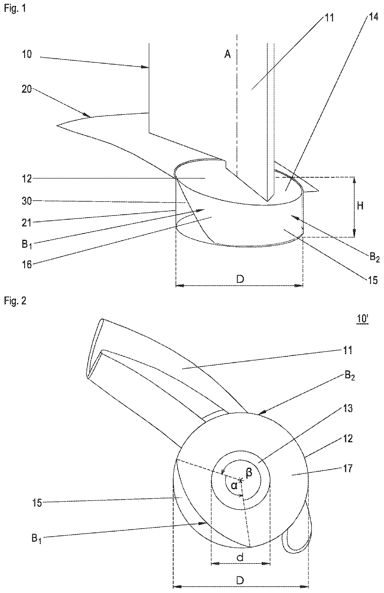
[0031]A section of a guide vane 10, which is inserted in a pivotable manner around a longitudinal axis A into an uptake 21 of an inner ring 20 (shown only in a section), is illustrated in a perspective illustration in FIG. 1. For better understanding, in this case, a view into the uptake 21 is shown in the illustration; the uptake is formed here as a straight circular cylinder, its central axis extending into the inner ring in the radial direction (of the inner ring).

[0032]The guide vane 10 has a vane element 11 and a guide vane plate 12. The guide vane plate 12 has a diameter D and an average thickness (or height) H (as the length of the section of the longitudinal axis A running between the cover surface and the base surface in the guide vane plate), which is smaller than the diameter. The guide vane plate further has a cover surface 14 facing the vane element 11, a base surface which is covered up in FIG. 1, and an edge surface 15 joining the cover surface and the base surface. I...


PUM


Abstract

A guide vane according to the invention for a guide vane ring of a turbomachine has a vane element as well as a guide vane plate for its support on an inner ring. The guide vane plate has a cover surface facing the vane element, a base surface lying opposite to the cover surface, and an edge surface joining the cover and base surfaces. In a first region, the edge surface forms a chamfer of the vane plate, and in a second region, which forms the edge of a sector of the guide vane plate that is different from that of the first region, the edge surface runs along a cylindrical surface. A method comprises inserting a plurality of guide vanes according to the invention into respective uptakes in an inner ring.

Description

BACKGROUND OF THE INVENTION[0001]The invention relates to a guide vane for a guide vane ring of a turbomachine, a guide vane ring for a turbomachine, and a method for assembling a guide vane ring.[0002]For establishing optimal operating conditions, turbomachines such as aircraft engines and stationary gas turbines often have, on the compressor side, at least one row of guide vanes having a plurality of guide vanes. Together with an inner ring the row of guide vanes forms a so-called guide vane ring. In this case, the guide vanes are preferably pivotable around their longitudinal axis.[0003]A radially outer support of the guide vanes on a housing or a housing part as well as a pivoting of the guide vanes can be provided via an outer vane plate at the guide vanes and, if needed, adjusting pins or journals for each vane connecting thereon, these pins being inserted into uptakes in the housing associated with them and being able to interact with a corresponding adjustment device on the ...

Claims


Application Information

Patent Timeline
Patent Type & Authority Patents(United States)
IPC IPC(8): F01D9/04F01D17/16F04D29/56F04D29/64
CPCF01D9/041F01D17/162F04D29/563F04D29/644F05D2220/32F05D2220/36F05D2230/60F05D2240/80F05D2250/192F05D2250/71
Inventor STIEHLER, FRANK
Owner MTU AERO ENGINES GMBH
Why Eureka
Try Eureka