Uncontrolled alternating-current demagnetiser

a demagnetiser and alternating-current technology, which is applied in the direction of electrical equipment, magnetic bodies, relays, etc., can solve the problems of undiscovered errors, inability to move continuously with as constant a distance as possible from the component, and undesired residual magnetic fields in the componen

Inactive Publication Date: 2015-12-24
MAURER ALBERT
View PDF2 Cites 0 Cited by
  • Summary
  • Abstract
  • Description
  • Claims
  • Application Information

AI Technical Summary

Problems solved by technology

As this erroneous treatment of the component cannot be seen and often there are no magnetic field measuring devices present for investigating the demagnetisation, these errors remain undiscovered.
Owing to the high magnetic alternating field, a continuous movement with as constant a distance as possible from the component is often not easily possible.
Here also, undesired residual magnetic fields remain in the component.
The resulting disruptive residual magnetic field is generally

Method used


Image

  • Uncontrolled alternating-current demagnetiser
  • Uncontrolled alternating-current demagnetiser

Examples


Embodiment Construction

[0013]The object of the present invention is to create simple and cost-effective uncontrolled alternating-current demagnetisers, using which the susceptibility to errors is minimised during demagnetisation, even by users who have no idea of the processes during demagnetisation.

[0014]The solution according to the invention can be integrated into conventional handheld, plate or tunnel demagnetisers with little additional outlay. The considerably more complicated and more expensive variant with external power modules or control devices for pulse / ramp control is therefore dispensed with.

[0015]Good process reliability is achieved by means of the uncontrolled alternating-current demagnetiser according to the invention, incorrect operation being minimised.

SHORT DESCRIPTION OF THE DRAWINGS

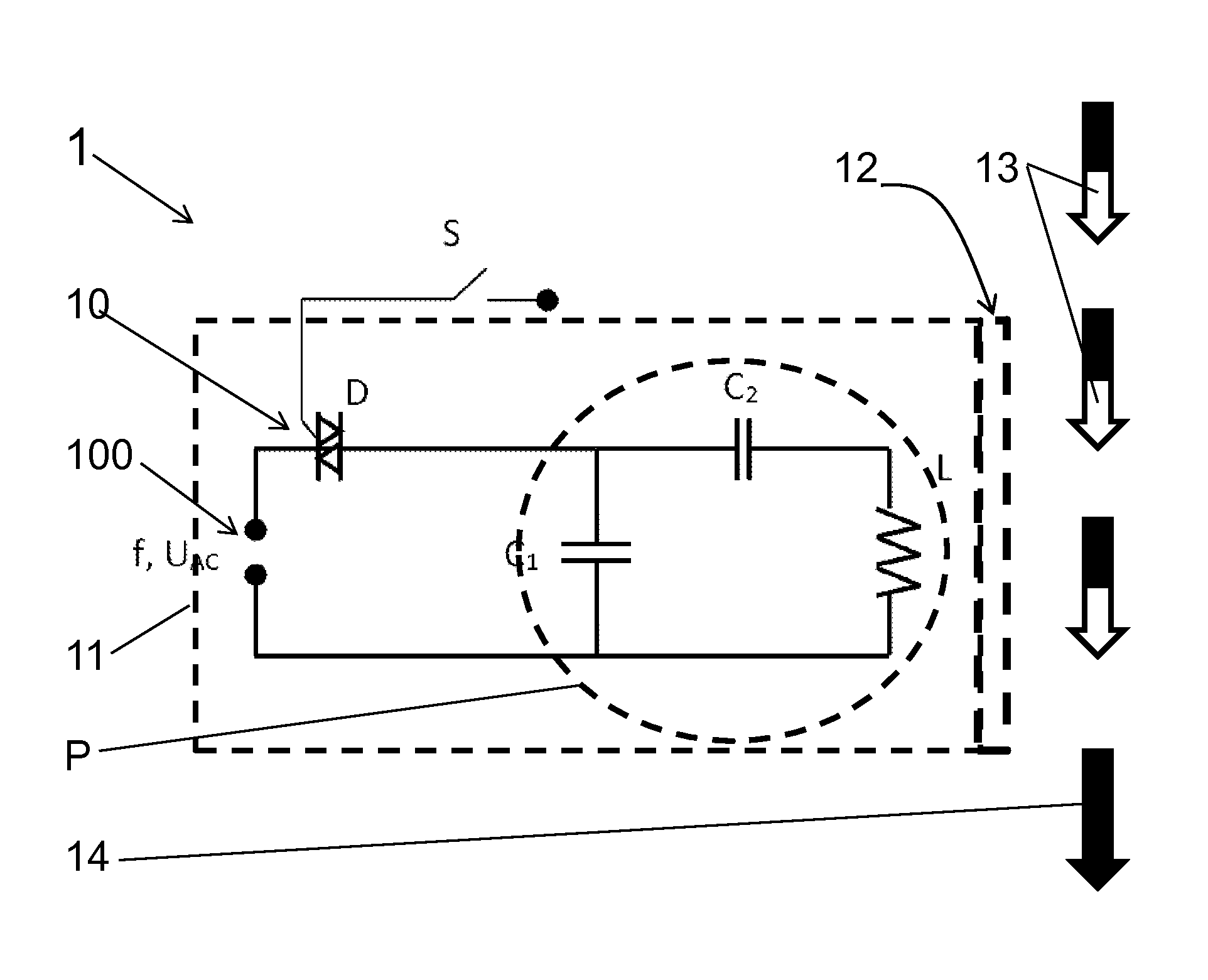
[0016]A preferred exemplary embodiment of the subject of the invention is described in the following in connection with the attached drawings.

[0017]FIG. 1 shows a schematic view of an electronic circuit of...


PUM


Abstract

For an uncontrolled alternating-current demagnetiser (1), comprising an alternating-current circuit (10) and an AC voltage source (100), wherein the alternating-current circuit (10) allows the AC voltage loading, by means of the actuation of a switch (S), of a parallel resonant circuit (P) comprising a demagnetising coil (L) and a parallel capacitor (C1) connected in parallel to the demagnetising coil (L), the option should be created to minimise the error proneness during demagnetisation, even of users, who do not have any knowledge of the processes during the demagnetisation. This is achieved in that the alternating current in the inductance L freely decays when the semiconductor element D is switched off. To limit the inrush current owing to the parallel capacitor C1, at least one electronic component (D) is arranged in series to the AC voltage source (100) and can be operated by means of switch (S). The alternating-current circuit (10) is in this case switched on exactly at the zero passage of the AC voltage source (100). A series capacitor (C2) is expediently connected in series with the demagnetising coil (L) in the alternating-current circuit (10).

Description

TECHNICAL FIELD[0001]The present invention describes an uncontrolled alternating-current demagnetiser, comprising an alternating-current circuit and an AC voltage source, wherein the alternating-current circuit allows the AC voltage loading, by means of the actuation of a switch, of a parallel resonant circuit comprising a demagnetising coil and a parallel capacitor connected in parallel to the demagnetising coil.PRIOR ART[0002]For a long time, uncontrolled alternating-current demagnetisers have been used for demagnetising ferromagnetic components or components with ferromagnetic contents.[0003]An alternating current flow through at least one inductance is created by means of an AC voltage, which conventionally alternates with network frequency, and, as a result, an alternating magnetic field is created in the surroundings of the inductance. In order to create satisfactorily high alternating magnetic fields, the uncontrolled alternating-current demagnetiser must be designed in such ...

Claims


Application Information

Patent Timeline
IPC IPC(8): H01F13/00
CPCH01F13/006
Inventor MAURER, JR., ALBERTROHNER, MAREKZIEGENHAGEN, BORIS
Owner MAURER ALBERT
Why Eureka
Try Eureka