90-degree phase shifter

a phase shifter and 90 degree technology, applied in pulse manipulation, pulse modulation carrier system, pulse technique, etc., can solve the problems of deviating from 90 degree, affecting the way it is fed back, and not always yielding output signals with a phase difference of exactly 90 degr

Inactive Publication Date: 2008-03-11
SHARP KK
View PDF9 Cites 1 Cited by
  • Summary
  • Abstract
  • Description
  • Claims
  • Application Information

AI Technical Summary

Benefits of technology

[0015]An object of the present invention is to provide a 90-degree phase shifter that more surely yields output signals with a phase difference of exactly 90 degrees.
[0027]Moreover, feeding back the phase deviations from 90 degrees as the currents produced by the first to fourth variable current sources minimizes the susceptibility to noise. Furthermore, now that the phase deviations from 90 degrees are fed back as currents, by making as short as possible the wiring from the phase comparator to the first to fourth variable current sources, even if the wiring from the nodes between the first to fourth input transistors and the dual differential circuit to the first to fourth variable current sources is long, it is possible to minimize the susceptibility to the voltage drops across the wiring resistances of the paths by way of which the phase deviations from 90 degrees need to be fed back. In this way, it is possible to more surely yield output signals with a phase difference of exactly 90 degrees.
[0028]In the 90-degree phase shifter configured as described above, a low-pass filter may be provided between the phase comparator and the first to fourth variable current sources. With this configuration, it is possible to eliminate the alternating-current component contained in the output signals of the phase comparator. This makes it possible to perform feedback control accurately according to the results of the phase comparison by the phase comparator. In this way, it is possible to yield output signals with a phase difference of more exactly 90 degrees.
[0029]In any of the 90-degree phase shifters configured as described above, an amplifier may be provided between the phase comparator and the first to fourth variable current sources. With this configuration, it is possible to increase the loop gain of the feedback loop, and thus to perform feedback control with high accuracy. In this way, it is possible to yield output signals with a phase difference of more exactly 90 degrees.

Problems solved by technology

On the other hand, if the input signal contains any DC offset and / or distortion, or if the circuit elements that constitute the T flip-flop have variations in their characteristics among them, the phase difference between the two output signals, undesirably, deviates from 90 degrees.
First, since the phase deviation from 90 degrees is fed back as a voltage, how it is fed back tends to be influenced by noise.
Hence, under the influence of noise or of the voltage drop across the wiring resistance as described above, the conventional 90-degree phase shifter shown in FIG. 6, inconveniently, does not always yield output signals with a phase difference of exactly 90 degrees.

Method used


Image

  • 90-degree phase shifter
  • 90-degree phase shifter
  • 90-degree phase shifter

Examples


Embodiment Construction

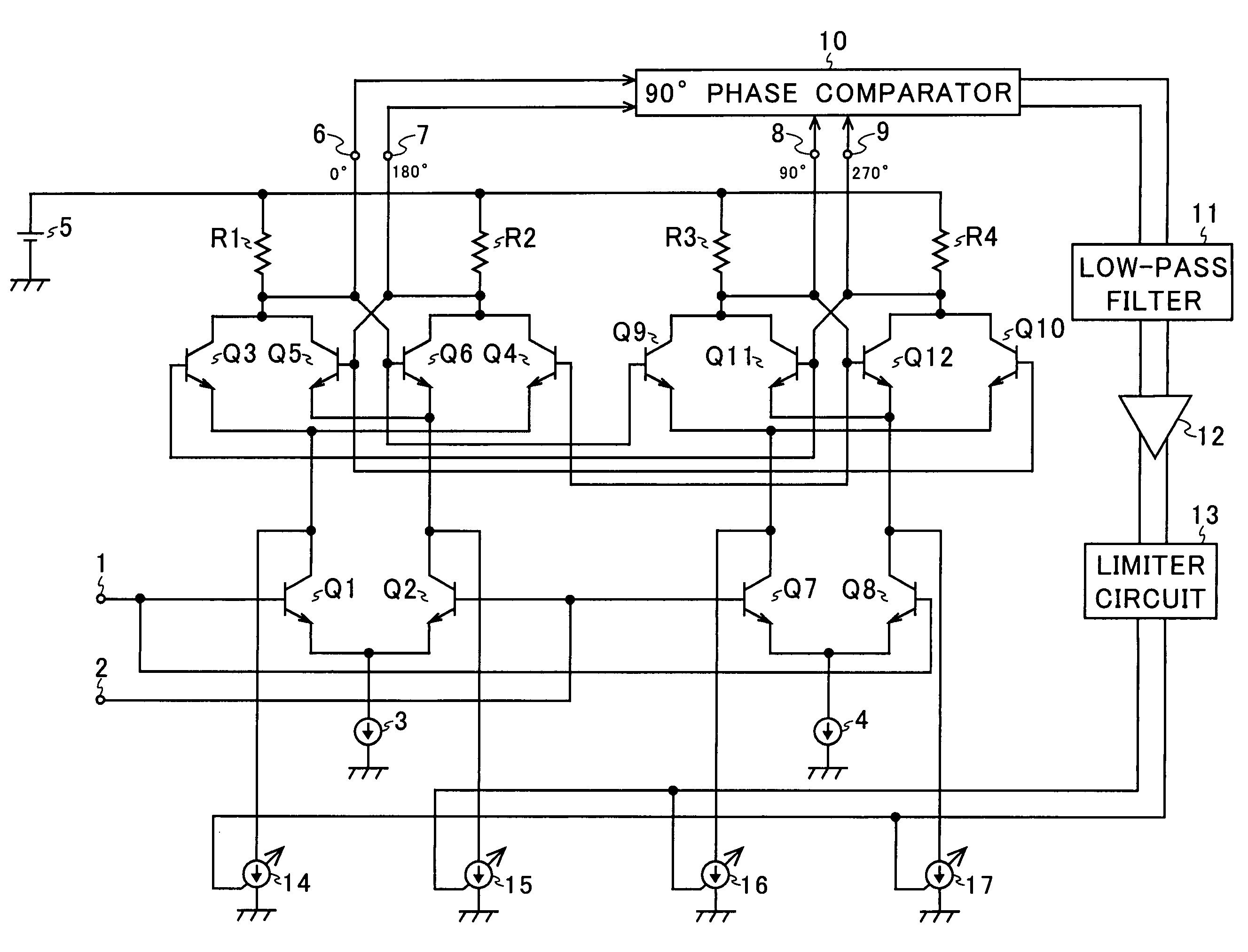
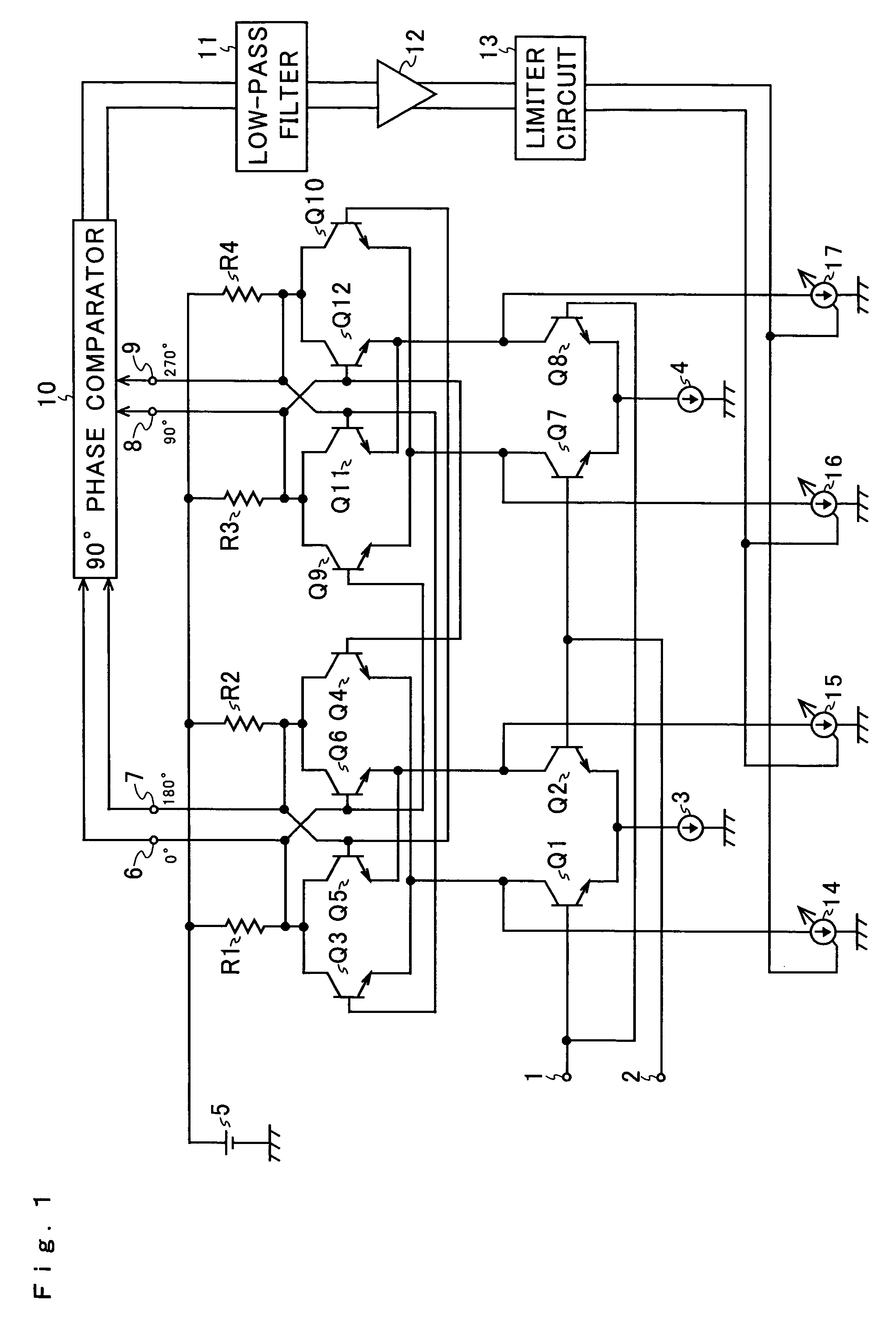
[0037]Hereinafter, an embodiment of the present invention will be described with reference to the accompanying drawings. An example of the configuration of a 90-degree phase shifter according to the invention is shown in FIG. 1. In FIG. 1, such circuit elements as find their counterparts in FIG. 6 are identified with common reference numerals or symbols.

[0038]As compared with the conventional 90-degree phase shifter shown in FIG. 3, the 90-degree phase shifter according to the invention shown in FIG. 1 is additionally provided with a 90-degree phase comparator 10, a low-pass filter 11, a DC amplifier 12, a limiter circuit 13, and variable current sources 14 to 17.

[0039]NPN-type transistors Q1 to Q12, input terminals 1 and 2, constant current sources 3 and 4, resistors R1 to R4, a constant voltage source 5, and output terminals 6 to 9 together constitute a T flip-flop that functions as a ½ frequency divider. The input terminal 1 is connected to the base of the input transistor Q1 and...


PUM


Abstract

The 90-degree phase shifter of the invention has: a T flip-flop including transistors Q3 to Q6 and Q9 to Q12 that together constitute a dual differential circuit, input transistors Q1 and Q2 that receive at their bases an input signal, and input transistors Q7 and Q8 that receive at their bases a signal complementary to the input signal; variable current sources 14 to 17 connected respectively to the nodes between the individual input transistors and the dual differential circuit; and a 90-degree phase comparator 10 that compares the phase differences between the signals outputted from the T flip-flop to output signals commensurate with the deviations of those phase differences from 90 degrees. The variable current sources 14 to 17 are controlled by signals based on the signals outputted from the 90-degree phase comparator 10. This configuration more surely yields output signals with a phase difference of exactly 90 degrees.

Description

[0001]This nonprovisional application claims priority under 35 U.S.C. § 119(a) on Patent Application No. 2003-413635 filed in Japan on Dec. 11, 2003, the entire contents of which are hereby incorporated by reference.BACKGROUND OF THE INVENTION[0002]1. Field of the Invention[0003]The present invention relates to a 90-degree phase shifter, and more particularly to a 90-degree phase shifter that is built using a T flip-flop.[0004]2. Description of Related Art[0005]An example of the configuration of a conventional 90-degree phase shifter is shown in FIG. 3. The conventional 90-degree phase shifter shown in FIG. 3 is a 90-degree phase shifter built using a T flip-flop, and is composed of transistors Q1 to Q12, resistors R1 to R4, input terminals 1 and 2, constant current sources 3 and 4, a constant voltage source 5, and output terminals 6 to 9.[0006]When an input signal having a predetermine frequency and having a duty factor of 50% is fed in via the input terminal 1, the input transisto...

Claims


Application Information

Patent Timeline
Patent Type & Authority Patents(United States)
IPC IPC(8): H04L23/00H03H11/18H03H11/16H03H11/22H03K3/2885H03K17/60
CPCH03H11/22H03K3/2885H03K17/603
Inventor ASHIDA, NOBUYUKI
Owner SHARP KK
Why Eureka
Try Eureka