
Method for performing measurements using a test element in a coordinate measuring machine or a machine tool

a technology of coordinate measuring machine and test element, which is applied in the direction of mechanical measuring arrangement, instruments, manufacturing tools, etc., to achieve the effect of increasing reliability and minimizing the susceptibility to errors

Active Publication Date: 2017-06-22
CARL ZEISS IND MESSTECHN GMBH
View PDF1 Cites 3 Cited by
  • Summary
  • Abstract
  • Description
  • Claims
  • Application Information

AI Technical Summary

Benefits of technology

The invention solves the problem of using an expensive and highly accurate polygon for measurements by replacing it with a single mirror that can be rotated and / or offset by a specific angle and / or distance for each measurement. This allows for more measurements to be performed in each new angle position, exceeding the number of measurements possible with a polygon. The use of a simple mirror offers a cost-effective option for replacing a highly accurate polygon. The test element can be coupled to a movement device with a three-point mounting or a repeatable, accurate, and stable positioning. The test element can also have an identification feature, such as an electronically readable identification feature, to minimize errors and increase reliability.

Problems solved by technology

The error is in particular a movement error or motion error of the coordinate-measuring machine or a rotation position error of the rotating apparatus, in particular an error of the rotation position ascertaining system with which the rotational position of part of the rotating apparatus is measurable.

Method used


Image

  • Method for performing measurements using a test element in a coordinate measuring machine or a machine tool
  • Method for performing measurements using a test element in a coordinate measuring machine or a machine tool
  • Method for performing measurements using a test element in a coordinate measuring machine or a machine tool

Examples


Embodiment Construction

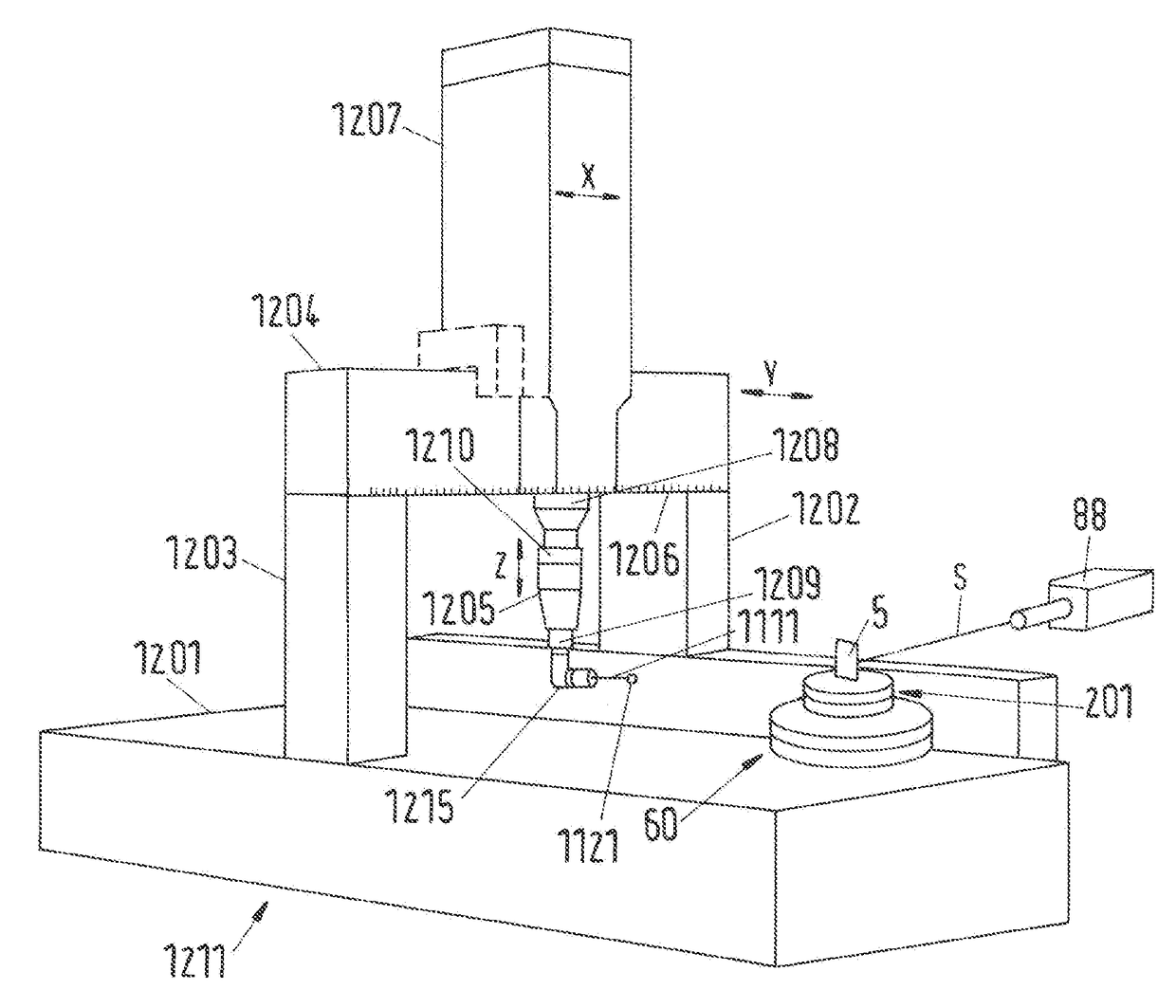
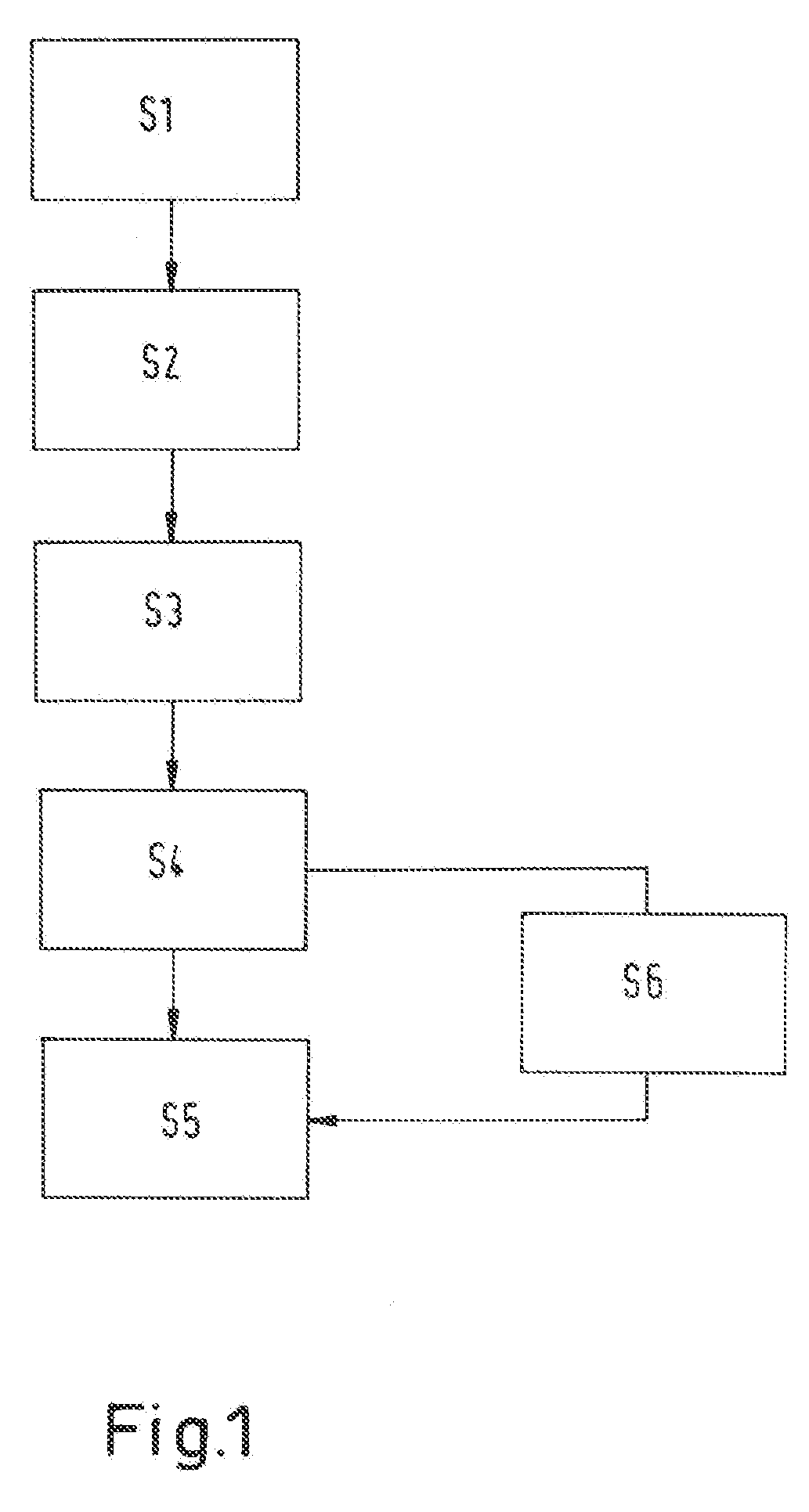
[0075]FIG. 1 schematically illustrates a method sequence according to the invention:

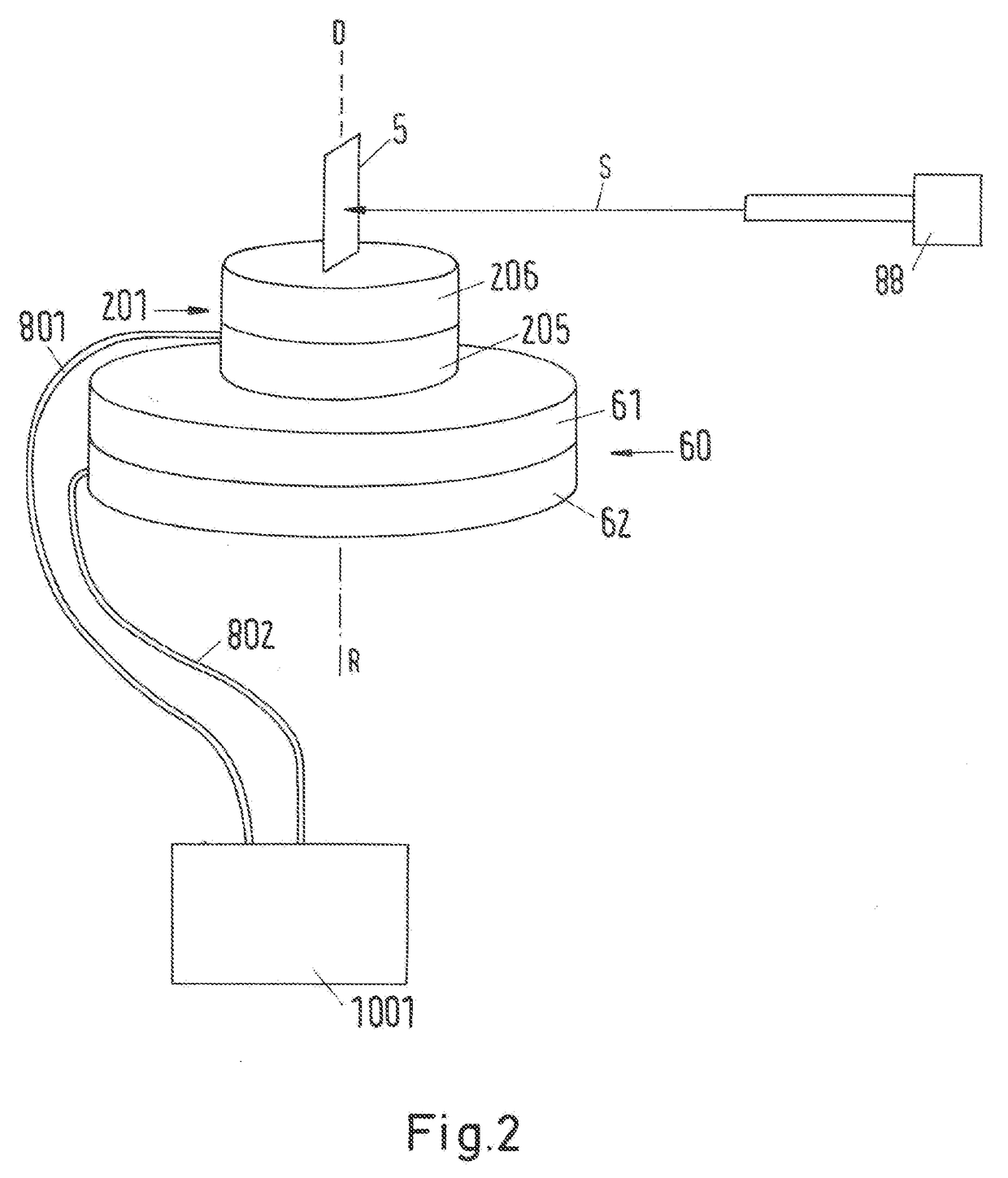
[0076]Step S1: arranging a test element in a measurement region of a coordinate-measuring apparatus, wherein the test element is arranged on a base of the coordinate-measuring apparatus or at / on a first, rotatable part of a rotating apparatus arranged within the measurement region, and wherein the test element is arranged in a first pose relative to the base or to the first part.

[0077]Step S2: performing a measurement by incorporating the test element in the first pose.

[0078]Step S3: coupling the test element to a sensor movement device of the coordinate-measuring apparatus, in particular to a probe.

[0079]Step S4: arranging the test element with the sensor movement device in a second pose on the base or on the first part using the sensor movement device.

[0080]Step S5: performing a measurement by incorporating the test element in the second pose.

[0081]As an alternative to performing step S5 after step...


PUM


Abstract

A method for performing measurements using a test element, comprising:arranging a test element in a measurement region of a coordinate-measuring apparatus, wherein the test element is arranged on a base of the coordinate-measuring apparatus or at / on a first, rotatable part of a rotating apparatus arranged within the measurement region, and wherein the test element is arranged in a first pose relative to the base or to the first part.performing a measurement by incorporating the test element in the first pose,arranging the test element with the movement device in a second pose on the base or on the first part using the movement device,performing a measurement by incorporating the test element in the second pose.

Description

CROSS-REFERENCE TO RELATED APPLICATION[0001]The present application claims priority under 35 U.S.C. § 119 to German national application, No. 10 2015 226 387.8, filed Dec. 21, 2015, the entire contents of which are incorporated herein by reference.BACKGROUND OF THE INVENTION[0002]The present invention relates to a method for performing measurements using a test element in a coordinate-measuring machine or machine tool, wherein the test element in the method is arranged in a different pose.[0003]The accuracy requirements relating to the positioning of rotation axes, for example rotatable joints or rotating apparatuses, which are used in coordinate-measuring machines (CMM) or machine tools, frequently exceed the accuracies of the measuring systems of the rotation axes, for example of an angle-measuring system. It is therefore customary to capture the error of the measuring system or of a scale which is contained therein in a suitable fashion and to correct it downstream, for example d...

Claims


Application Information

Patent Timeline
Patent Type & Authority Applications(United States)
IPC IPC(8): G01B5/24G01B5/008
CPCG01B5/008G01B5/24G01B21/04B23Q3/183B23Q17/2291G01B21/042
Inventor SEITZ, DOMINIKSAGEMUELLER, RAINER
Owner CARL ZEISS IND MESSTECHN GMBH
Learn More