
Light wavelength meter

a wavelength meter and light technology, applied in the field of light wavelength meter, can solve the problems of complex operation principle, limited measurement resolution of other systems, and difficult to set-up and maintain, and achieve the effect of simple and economical, low cost of wavelength meter, and easy setup and maintenan

Inactive Publication Date: 2005-02-22
TRANSPACIFIC LASERIA
View PDF31 Cites 3 Cited by
  • Summary
  • Abstract
  • Description
  • Claims
  • Application Information

AI Technical Summary

Benefits of technology

An advantage of the present invention is that it is simpler and economical. Due to its use of fewer components in a single pass arrangement, the wavelength meter is easily set-up and maintained. Its use of fewer components, and particularly providing its ability to avoid the use of more complex components, such as curved gratings, keeps the cost of the wavelength meter low.
is that it is simpler and economical. Due to its use of fewer components in a single pass arrangement, the wavelength meter is easily set-up and maintained. Its use of fewer components, and particularly providing its ability to avoid the use of more complex components, such as curved gratings, keeps the cost of the wavelength meter low.
Another advantage of the invention is that it may be implemented using either a transmissive or reflective light diverter, and a wide range of suitable light diverters may be chosen from to facilitate different goals. For example, transmissive or reflective diffraction gratings or multiple slit plates may be used. One diffraction grating can be used where it is desired to work with multiple channels concurrently. Or a multiple slit plate, optionally with simple a light diverger, can provide an economical arrangement.
Another advantage of the invention is that it may be implemented with a light diverger to enhance resolution, and the range of potential light divergers is broad and may therefore facilitate different goals. The light diverger may also be either transmissive or reflective, particularly facilitating constructing the wavelength meter in a variety of manners. In some embodiments overall compactness can be emphasized and in others susceptibility to undesirable influences can be minimized, like structural change due to temperature variation.
Another advantage of the invention is that it may be implemented with sophisticated signal processing techniques, such as phase sensitive detection, to further increase measurement accuracy and reliability.
And another advantage of the invention is that it solves a pressing and current need in at least one increasingly critical industry, telecommunications.

Problems solved by technology

Numerous systems exist to measure wavelength or frequency in some manner, these suffer from a number of limitations.
Other systems have limited measurement resolution.
Still others have complex principals of operation: requiring moving or complex parts, which typically are expensive; or requiring multiple passes through at least part of the optics.
In fact, most prior art systems suffer from combinations of these, and summaries of some such systems follow.
As such, this reference merely addresses spectrum separation, albeit using a diffraction grating and other optical components to achieve this, but it is not otherwise particularly relevant.
As such, this system also employs physically moving sub-systems which are difficult to set up, calibrate, and maintain.
Unfortunately, however, the transmittance of its optical filter is too wavelength specific.
That is to say that it is useful for locking to a specific frequency but not so useful for measuring what wavelength is present.
The placement of the beam expander before the reflecting grating introduces a number of problems.
The reflecting grating must accept an expanded beam and thus must be physically larger, and accordingly more expensive.
In sum, the state of the art systems are too complex.
They are expensive, difficult to use and maintain, and not as accurate as desired.

Method used


Image

  • Light wavelength meter
  • Light wavelength meter
  • Light wavelength meter

Examples


embodiment 300

FIG. 7 is a block diagram presenting a multiple slit embodiment 300 of the inventive wavelength meter 10. A light source (not shown) produces a light beam 314, having a first beam portion 314a and a second beam portion 314b. The first beam portion 314a is received at a slit plate 316 (serving here as a transmissive light diverter) which imparts to the second beam portion 314b a transverse displacement characteristic. The second beam portion 314b is, in turn, received by a diverging lens 318 (used as a light diverger for angular resolution extension here) and produces a third beam portion 314c. A light detection unit 320 then detects aspects of the transverse displacement in the third beam portion 314c and produces a raw signal which is representative thereof. With techniques and components described elsewhere herein, this raw signal can then be appropriately processed to meter the wavelength or lock the frequency in the light beam 314.

Aside from the alternate type of light diverter ...

embodiment 400

FIG. 8 is a block diagram presenting an acousto-optical embodiment 400 of the inventive wavelength meter 10. A light source (not shown) produces a light beam 414, having a first beam portion 414a and a second beam portion 414b. The first beam portion 414a is received at an acousto-optical unit 416 (serving here as a transmissive light diverter) which imparts to the second beam portion 414b a transverse displacement characteristic. A light detection unit 420 then detects aspects of the transverse displacement in the second beam portion 414b and produces a raw signal which is representative thereof. With techniques and components described elsewhere herein, this raw signal can then be appropriately processed to meter the wavelength or lock the frequency in the light beam 414.

The acousto-optical unit 416 includes an acousto-optic crystal, such as LiNbO3, ADP, KDP, etc. In the acousto-optic crystal the light beam 414 is modulated by interaction with sound waves, typically created by a p...


PUM


Abstract

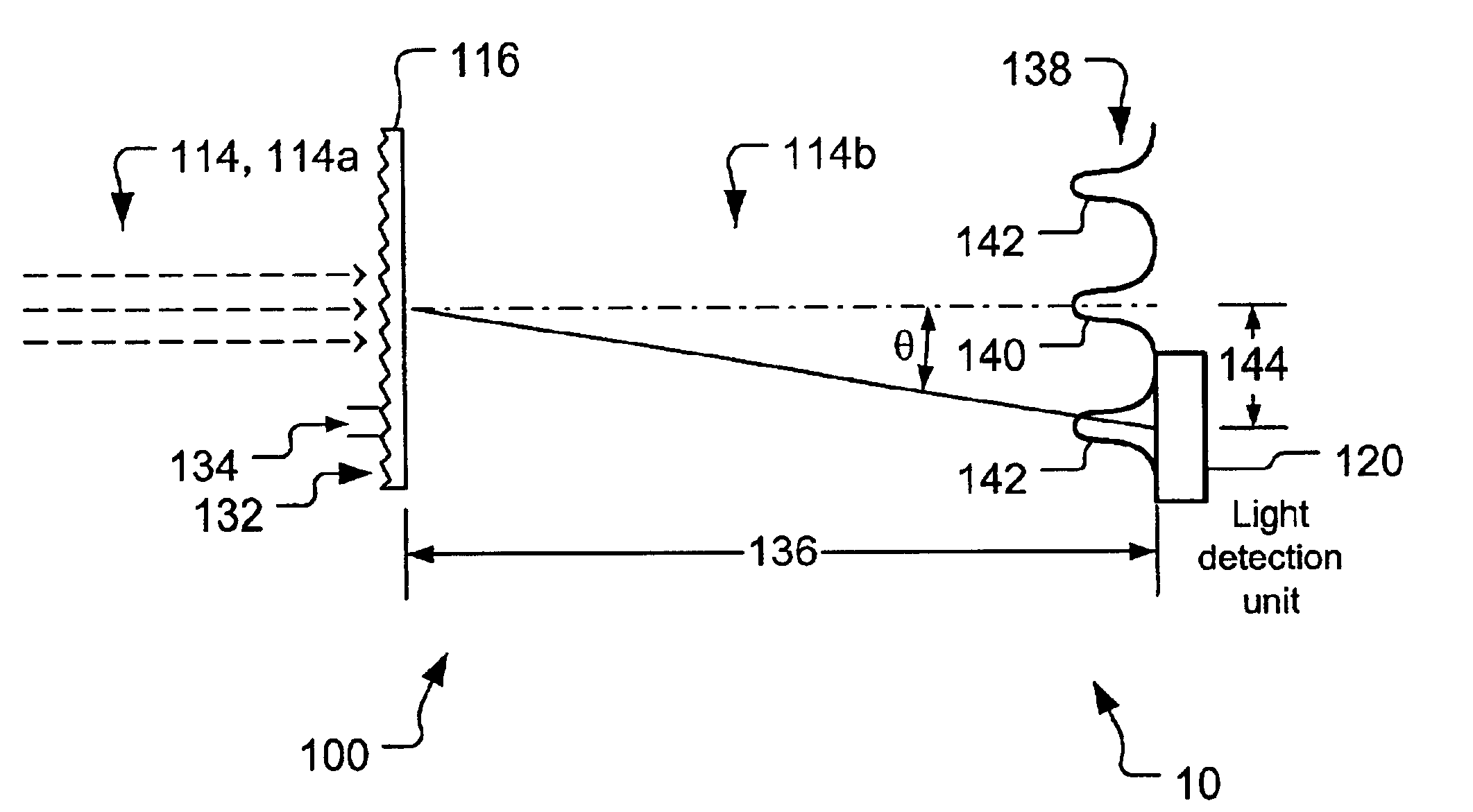
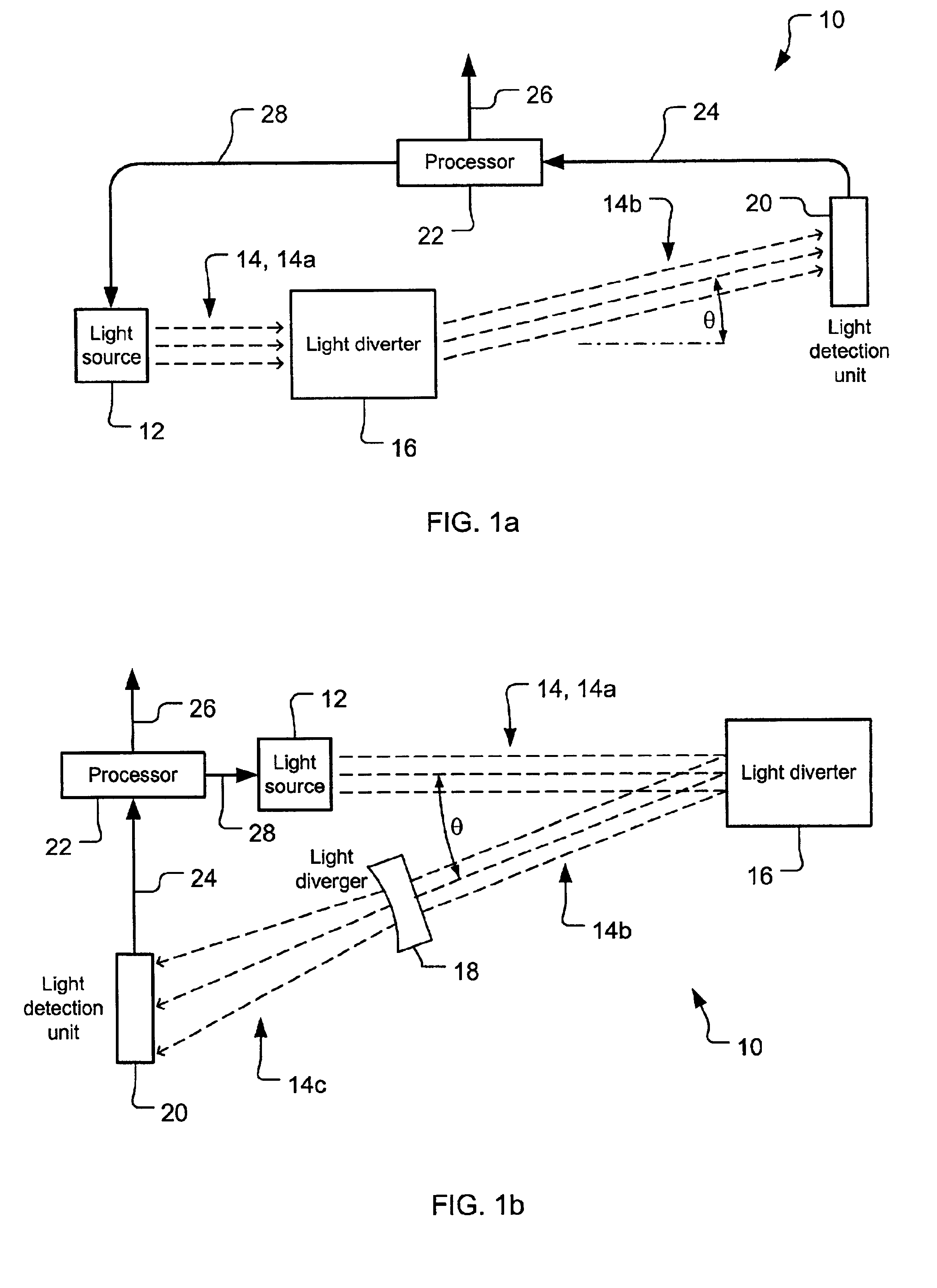
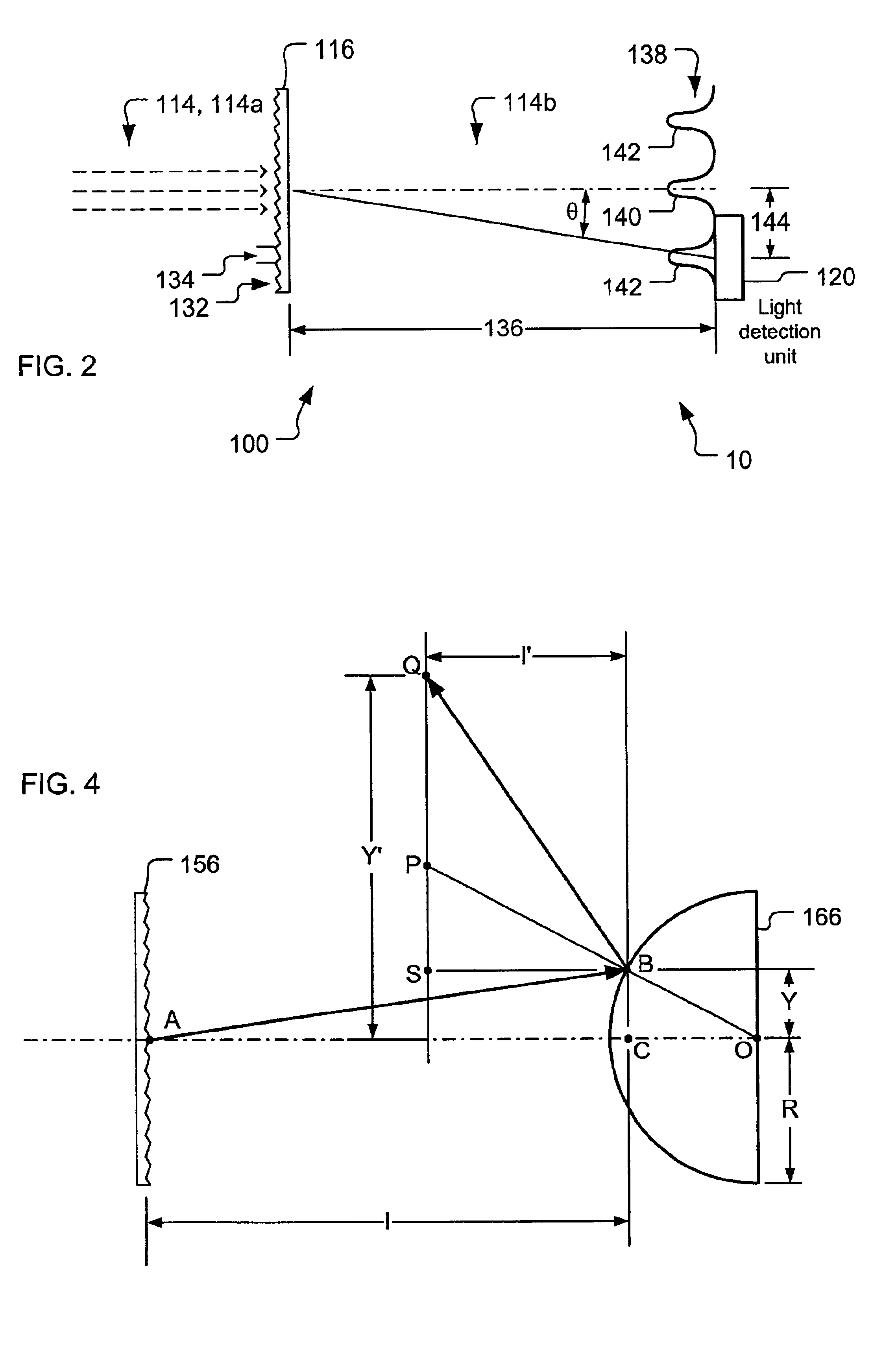
A light wavelength meter (10) able to accept light into a light diverter (16) and impart to it a transverse displacement characteristic which can be detected in a light detection unit (20) connected to a processor (22). Optionally, a light diverger (18) may be provided to enhance angular resolution. The light diverter (16) and the light diverger (18) may either transmit or reflect the light. The light diverter (16) may particularly include a diffraction grating (116, 156), Fabry-Perot interferometer (216), multiple slit plate (316), or an acousto-optical unit (416).

Description

TECHNICAL FIELDThe present invention relates generally to methods and apparatus for using, controlling and detecting radiant energy, and more particularly to light wavelength determination. It is anticipated that the present invention will be employed widely in the calibration of light wavelength and the stabilization of light frequency, particularly in the telecommunications industry, but the invention is also well suited for use in laboratory measurement and in many other industries.BACKGROUND ARTThe ability to measure the wavelength or frequency (herein treated as equivalent with both meant when either term is used) of light is highly useful in industry and basic research. The telecommunications industry provides an excellent example, and will be used as the one herein. One brief discussion of the need for this capability in telecommunications can be found in REIZEMAN. “Optical Nets Brace for Even Heavier Traffic,” IEEE Spectrum, Jan. 2001. pg. 44-46. discussing the growth of wav...

Claims


Application Information

Patent Timeline
Patent Type & Authority Patents(United States)
IPC IPC(8): G01J3/26G01J3/12G01J9/00H01S3/13H04B10/155H04B10/152H04B10/08G01J9/02
CPCG01J3/26G01J9/00H04B10/572H04B10/07H04B10/503H01S3/13G01J2009/0257
Inventor TSAI, JOHN C.
Owner TRANSPACIFIC LASERIA
Learn More