Observation device, observation method, and observation device control program

a technology of observation device and control program, which is applied in the field of observation device, observation method, and non-transitory computer readable recording medium, can solve the problems of inability to perform high-speed imaging, inability to perform appropriate auto-focus control, and out-of-focus image, and achieve high accuracy

Active Publication Date: 2021-11-02
FUJIFILM CORP
View PDF15 Cites 2 Cited by
  • Summary
  • Abstract
  • Description
  • Claims
  • Application Information

AI Technical Summary

Benefits of technology

[0007]Here, in a case where the image for each observation position is captured as described above, there are many cases where a focal position of the imaging optical system is adjusted on a bottom surface of the cultivation container. However, the thickness of a bottom portion of the cultivation container has a millimeter-order fabrication tolerance, and thus, in a case where high-magnification imaging is performed, it is necessary to adjust the focal position for each observation position. On the other hand, it is desirable that a cell imaging time is short, and thus, it is desirable to provide a device capable of performing high-speed imaging.
[0010]In consideration of the above-mentioned problems, an object of the present invention is to provide an observation device, an observation method, and a non-transitory computer readable recording medium storing an observation device control program capable of performing an auto-focus control with high accuracy, without being affected by a vertical position change based on movement of a stage.
[0022]According to the observation device, the observation method, and the non-transitory computer readable recording medium storing an observation device control program of the invention, before an observation region of an imaging optical system reaches an observation position in a container, a vertical position of the container at the observation position is precedently detected using an auto-focus displacement sensor. In a case where an objective lens of the imaging optical system is moved in an optical axis direction on the basis of the detected vertical position of the container, an error between a vertical position of a stage at the observation position precedently detected by the auto-focus displacement sensor, and a vertical position of the stage at a time point when the observation region of the imaging optical system is scanned up to the observation position is acquired, and the observation position is scanned by the observation region of the imaging optical system. Further, the objective lens is moved in the optical axis direction on the basis of the acquired error and the vertical position of the container at the observation position that is detected by the auto-focus displacement sensor, in scanning the observation position in the observation region of the imaging optical system. Thus, it is possible to perform an auto-focus control with high accuracy, without being affected by a vertical position change due to stage movement.

Problems solved by technology

However, in a related-art auto-focus control method, about 2 seconds are necessary for each observation position, and for example, in a case where the number of observation positions is 300, it takes 10 minutes only for a time necessary for an auto-focus control, which makes it impossible to perform high-speed imaging.
Further, as disclosed by JP2010-072017A, in a case where the Z-directional position of the XY stage at a time point when the Z-directional position of the well plate is detected by the displacement meter and the Z-directional position of the XY stage at a time point when the detected position in the displacement meter is moved to the position of the objective lens are different from each other, it is not possible to perform an appropriate auto-focus control due to an error of the Z-directional position of the XY stage, which results in an out-of-focus image.

Method used


Image

  • Observation device, observation method, and observation device control program
  • Observation device, observation method, and observation device control program
  • Observation device, observation method, and observation device control program

Examples


Embodiment Construction

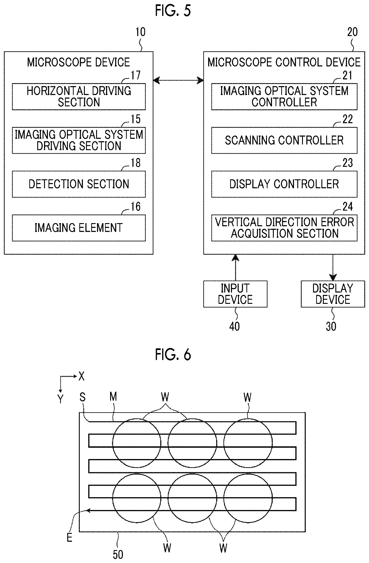
[0036]Hereinafter, a microscope observation system that uses an observation device, an observation method, and an observation device control program according to an embodiment of the invention will be described in detail with reference to the accompanying drawings. FIG. 1 is a block diagram showing a schematic configuration of a microscope device 10 in a microscope observation system of the embodiment.

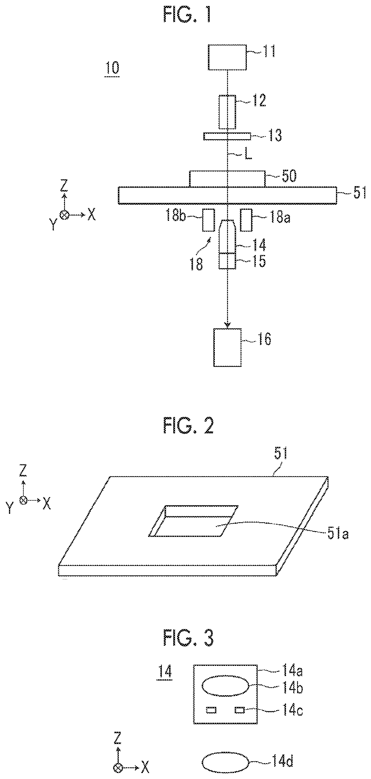
[0037]The microscope device 10 captures a phase difference image of a cultivated cell that is an observation target. Specifically, the microscope device 10 includes a white light source 11 that emits white light, a condenser lens 12, a slit plate 13, an imaging optical system 14, an imaging optical system driving section 15, an imaging element 16, and a detection section 18, as shown in FIG. 1.

[0038]Further, a stage 51 is provided between the slit plate 13, and the imaging optical system 14 and the detection section 18. A cultivation container 50 in which cells that are observation tar...


PUM


Abstract

Before an observation region of an imaging optical system (14) reaches an observation position in the cultivation container (50), a vertical position of the cultivation container (50) at the observation position is precedently detected by an auto-focus displacement sensor. In a case where an objective lens is moved in an optical axis direction on the basis of the position, an error between the precedently detected vertical position of the stage (51) at the observation position and a vertical position of the stage (51) at a time point when the observation region of the imaging optical system (14) is scanned up to the observation position is acquired, and the objective lens is moved in the optical axis direction on the basis of the error.

Description

CROSS-REFERENCE TO RELATED APPLICATIONS[0001]This application is a Continuation of PCT International Application No. PCT / JP2017 / 032930 filed on Sep. 12, 2017, which claims priority under 35 U.S.C § 119(a) to Japanese Patent Application No. 2016-189794 filed on Sep. 28, 2016. Each of the above application(s) is hereby expressly incorporated by reference, in its entirety, into the present application.BACKGROUND OF THE INVENTION1. Field of the Invention[0002]The present invention relates to an observation device, an observation method, and a non-transitory computer readable recording medium storing an observation device control program for observing an entire image of an observation target by moving a stage on which a container in which the observation target is contained is placed with respect to an imaging optical system that forms an image of the observation target.2. Description of the Related Art[0003]In the related art, a method for capturing an image of a multipotential stem cel...

Claims


Application Information

Patent Timeline
Patent Type & Authority Patents(United States)
IPC IPC(8): G02B21/00G02B21/26G02B7/28G02B21/14G02B21/24
CPCG02B21/26G02B7/28G02B7/285G02B21/14G02B21/245G02B7/32G02B21/24G02B21/36
Inventor SHIRAISHI, YASUSHI
Owner FUJIFILM CORP
Why Eureka
Try Eureka