Observation device, observation method, and observation device control program

a technology of observation device and control program, which is applied in the direction of microscopes, mountings, instruments, etc., can solve the problem of inability to perform high-speed imaging, and achieve the effect of high accuracy and high accuracy

Active Publication Date: 2020-08-13
FUJIFILM CORP
View PDF0 Cites 1 Cited by
  • Summary
  • Abstract
  • Description
  • Claims
  • Application Information

AI Technical Summary

Benefits of technology

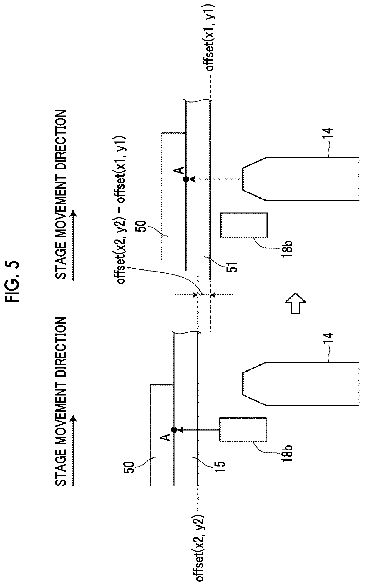
[0037]According to the observation device and method, and the observation device control program of the above aspects of the present invention, before the observation region of the imaging optical system reaches the observation position in the container, the vertical position of the container at the observation position is precedently detected by the auto-focus displacement sensor, and at least one of the first operation of changing the focal length of the imaging optical system, the second operation of moving the imaging lens in the optical axis direction, the third operation of moving the imaging element in the optical axis direction, or the fourth operation of moving the container in the optical axis direction is performed on the basis of the detected vertical position of the container. Here, the error between the vertical position of the container at the observation position that is precedently detected by the auto-focus displacement sensor and the vertical position of the container at the time point when the observation region of the imaging optical system is scanned up to the observation position is acquired, and at least one of the first operation to the fourth operation is performed by controlling the operation section, on the basis of the acquired error and the vertical position of the container at the observation position that is precedently detected by the auto-focus displacement sensor, when the observation position is scanned by the observation region of the imaging optical system. Accordingly, it is possible to perform an auto-focus control with high accuracy without being affected by a vertical position change due to the m...

Problems solved by technology

However, in a related-art auto-focus control method, about 2 seconds are necessary for each observation position, and for example, in a case where the number...

Method used


Image

  • Observation device, observation method, and observation device control program
  • Observation device, observation method, and observation device control program
  • Observation device, observation method, and observation device control program

Examples


Embodiment Construction

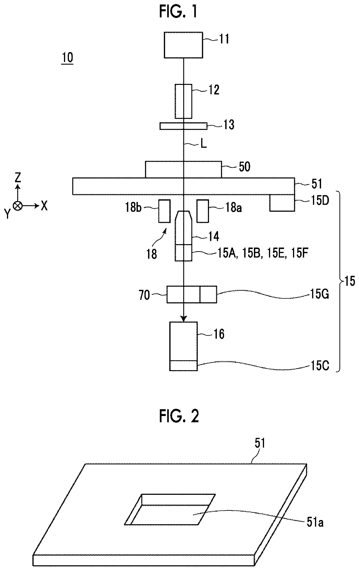
[0054]Hereinafter, a microscope observation system that uses an observation device, an observation method, and an observation device control program according to an embodiment of the invention will be described in detail with reference to the accompanying drawings. FIG. 1 is a block diagram showing a schematic configuration of a microscope device 10 in a microscope observation system of the embodiment.

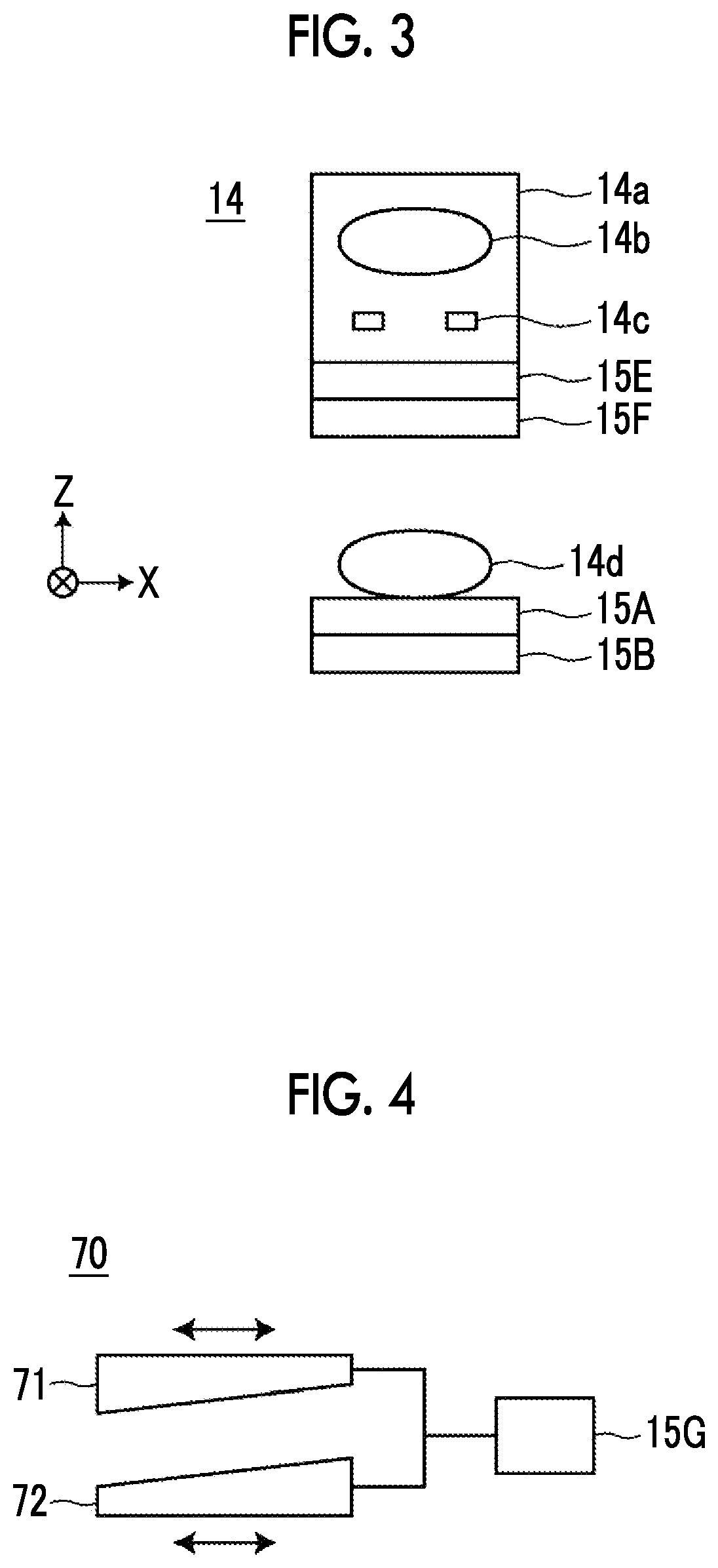
[0055]The microscope device 10 captures a phase difference image of a cultured cell that is an observation target. Specifically, as shown in FIG. 1, the microscope device 10 includes a white light source 11 that emits white light, a condenser lens 12, a slit plate 13, an imaging optical system 14, an operation section 15, an imaging element 16, and a detection section 18. Further, the microscope device 10 includes a focal length changing optical system 70.

[0056]The operation section 15 includes a first operation section 15A, a second operation section 15B, a third operation section 15C...


PUM


Abstract

Before an observation region of the imaging optical system reaches an observation position in a culture container, a vertical position of the culture container at the observation position is precedently detected by an auto-focus displacement sensor. In a case where an auto-focus control is performed on the basis of the position, an error between the precedently detected vertical position of the container at the observation position and a vertical position of the container at a time point when an observation region of the imaging optical system is scanned up to the observation position is acquired, and an objective lens is moved in an optical axis direction on the basis of the error.

Description

CROSS-REFERENCE TO RELATED APPLICATIONS[0001]This application is a Continuation of PCT International Application No. PCT / JP2018 / 041774 filed on Nov. 12, 2018, which claims priority under 35 U.S.C § 119(a) to Japanese Patent Application No. 2017-221444 filed on Nov. 17, 2017. Each of the above application(s) is hereby expressly incorporated by reference, in its entirety, into the present application.BACKGROUND OF THE INVENTION1. Field of the Invention[0002]The present invention relates to an observation device, an observation method, and an observation device control program for observing an entire image of an observation target by relatively moving a container in which the observation target is contained with respect to an imaging optical system that forms an image of the observation target.2. Description of the Related Art[0003]In the related art, a method for capturing an image of a multipotential stem cell such as an embryonic stem (ES) cell or an induced pluripotent stem (iPS) c...

Claims


Application Information

Patent Timeline
IPC IPC(8): G02B7/28G02B21/00G02B21/02G02B7/09G02B21/36
CPCG02B21/0036G02B7/282G02B7/09G02B21/006G02B21/008G02B21/362G02B21/025G02B21/26G02B21/34G02B21/367G02B21/14G02B21/0088G02B21/245G02B3/14
Inventor SHIRAISHI, YASUSHI
Owner FUJIFILM CORP
Why Eureka
Try Eureka