Transformable gamma cameras

a technology of gamma cameras and transformable gamma, which is applied in the field of gamma cameras, can solve the problems of less efficient detection, higher cost, and less efficient detection of czt 5 mm thick

Active Publication Date: 2020-11-12
KROMEK GRP PLC
View PDF4 Cites 1 Cited by
  • Summary
  • Abstract
  • Description
  • Claims
  • Application Information

AI Technical Summary

Benefits of technology

[0016]The most significant performance advantage for the smaller FOV gamma cameras is that the imaging efficiency can be increased, leading to either shorter imaging times, or lower injected radiation doses, or a combination of both lower time and dose. Although this advantage will be apparent to those skilled in the art, an illustration will illuminate this conclusion. Consider heart imaging with standard 40 cm×54 cm gamma cameras. At any time during the acquisition, two planar projection images of the heart are being acquired, one on each of the two gamma cameras deployed in a standard SPECT system. In an embodiment of the present invention, these two full-FOV cameras will subdivide into four half-FOV cameras. At any time during the SPECT acquisition, there will now be four planar projection images of the heart being acquired simultaneously. This will essentially double the efficiency of the imaging, enabling use of lower time and / or dose without any other changes required.
[0017]In one embodiment, general purpose SPECT imaging can be optimized by subdividing two large-FOV gamma cameras into four half-FOV cameras and orbiting these four cameras around the body in a step-and-shoot or continuous acquisition sequence, while each camera individually can approach the body outline as closely as possible (“body contouring”) to enhance spatial resolution.
[0018]In another embodiment, brain SPECT can be optimized by subdividing two large-FOV gamma cameras into four half-FOV cameras and orbiting these four cameras around the head in a step-and-shoot or continuous acquisition sequence, while each camera individually can approach the head outline as closely as possible to enhance spatial resolution.
[0019]In another embodiment, heart SPECT can be optimized by subdividing two large-FOV gamma cameras into four half-FOV cameras and orbiting these four cameras around the body in a step-and-shoot or continuous acquisition sequence, while each camera individually can approach the body outline as closely as possible to enhance spatial resolution and at the same time pointing toward the heart to increase efficiency.
[0020]In another embodiment, breast planar imaging (also known as molecular breast imaging) can be optimized by subdividing two large-FOV gamma cameras into four half-FOV cameras and placing a pair of half-FOV cameras in opposition next to each breast. Mild, non-painful compression between the two cameras will immobilize the breast. Multiple planar views can be acquired: for example, the two views most often used in mammography are the CC (cranial-caudal) and MLO (medial-lateral oblique) views. By imaging both breasts simultaneously, the clinical imaging time can be cut in half.
[0021]In a further embodiment of this present invention, the smaller-FOV gamma cameras can each wobble about their mechanical support axis to acquire projection data from a fan of angles. This acquisition strategy can reduce image reconstruction artifacts due to truncated views.

Problems solved by technology

One significant problem with state-of-the-art systems is that they are usually designed as “general purpose” SPECT systems in which many compromises have been made to accommodate different clinical applications, such as bone, brain, heart, or breast imaging.
These pixelated semiconductor detectors have many performance advantages over the monolithic scintillator and PMT prior art, but they also have the disadvantage of having a higher cost than the almost 60-year old prior art.
Increasing the CZT thickness to 1.0 cm will increase the stopping power and thus the detection efficiency for higher energy medical isotopes, such as In-111 (171 & 245 keV) and I-131 (364 keV), although they can be detected with 5 mm thick CZT, albeit less efficiently.
Moreover, the pixelated CZT gamma camera has no dead edges compared to the scintillation camera which has unusable (“dead”) edges about half the diameter of the PMTs wherein the Anger position determination is ineffective.

Method used


Image

  • Transformable gamma cameras
  • Transformable gamma cameras
  • Transformable gamma cameras

Examples


Embodiment Construction

"d_n">[0034]While the invention may be subject to embodiment in different forms, there is shown in the drawings, and herein will be described in detail, specific embodiments with the understanding that the present disclosure is to be considered an exemplification of the principles of the invention, and is not intended to limit the invention to that as illustrated and described herein.

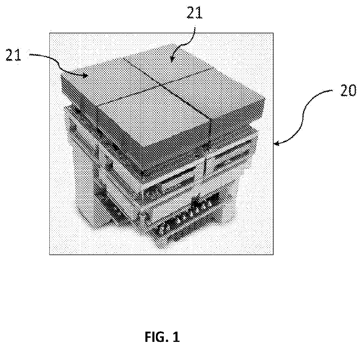
[0035]FIG. 1 shows a modular semiconductor direct conversion CZT gamma detector called D-Matrix™. This aggregator module (AM) 20 is composed of four CZT crystal detectors 21, each designated a gamma module (GM), each measuring about 2.2 cm×2.2 cm×0 5 cm thick. Each GM 21 may comprise a monolithic crystal or may comprise multiple tiles of CZT mounted in an abutting composite with small gaps between the tiles. The top GM 21 surface in FIG. 1 is the metallic cathode, which is typically monolithic but which can also be pixelated. Gamma photons generally enter the GUI from the cathode side of the CZT crystal...


PUM


Abstract

One embodiment provides a gamma camera system, including: a stand, a rotatable gantry supported by the stand, and a transformable gamma camera connected by mechanical supports to the rotatable gantry and comprising groups of tiled arrays of gamma detectors and a collimator for each group of tiled arrays of gamma detectors; the transformable gamma camera being configured to subdivide into a plurality of subdivided gamma cameras, each of the subdivided gamma cameras having at least one of the groups of tiled arrays of gamma detectors and corresponding collimator, wherein the subdivision into a plurality of subdivided gamma cameras facilitates contouring with a region of interest for a spatial resolution. Other embodiments are described and claimed.

Description

CROSS-REFERENCE TO RELATED APPLICATION[0001]This application is a continuation application of U.S. patent application Ser. No. 16 / 324,038 filed on Feb. 7, 2019 and titled “Transformable Gamma Cameras,” which is a national phase application of PCT / US17 / 45968 filed on Aug. 8, 2017 and titled “Transformable Gamma Cameras,” and claims priority from and benefit of U.S. Provisional Patent Application No. 62 / 372,007 filed on Aug. 8, 2016 and titled “Transformable Gamma Cameras,” all of which the subject matter of which is hereby incorporated by reference in its entirety.FIELD OF THE INVENTION[0002]The principle application addressed by this disclosure is Gamma Cameras, in general, and specifically Nuclear Medicine (aka “molecular Imaging”) which employs Single-Photon Emission Computed Tomography (SPECT) following injection of a radioisotope-labelled tracer (molecular imaging agent). The emitted gamma photons are imaged by a gamma camera, or preferably, a plurality of gamma cameras. In the ...

Claims


Application Information

Patent Timeline
Patent Type & Authority Applications(United States)
IPC IPC(8): A61B6/03G01T1/166G01T1/164A61B6/04A61B6/00G01T1/202A61B6/06G01T1/20
CPCA61B6/503A61B6/06A61B6/4258A61B6/4411A61B6/4233A61B6/501A61B6/502A61B6/4458G01T1/202A61B6/037A61B6/0414A61B6/4291G01T1/1642G01T1/2023G01T1/166G01T1/2006
Inventor HUGG, JAMES W.
Owner KROMEK GRP PLC
Why Eureka
Try Eureka