

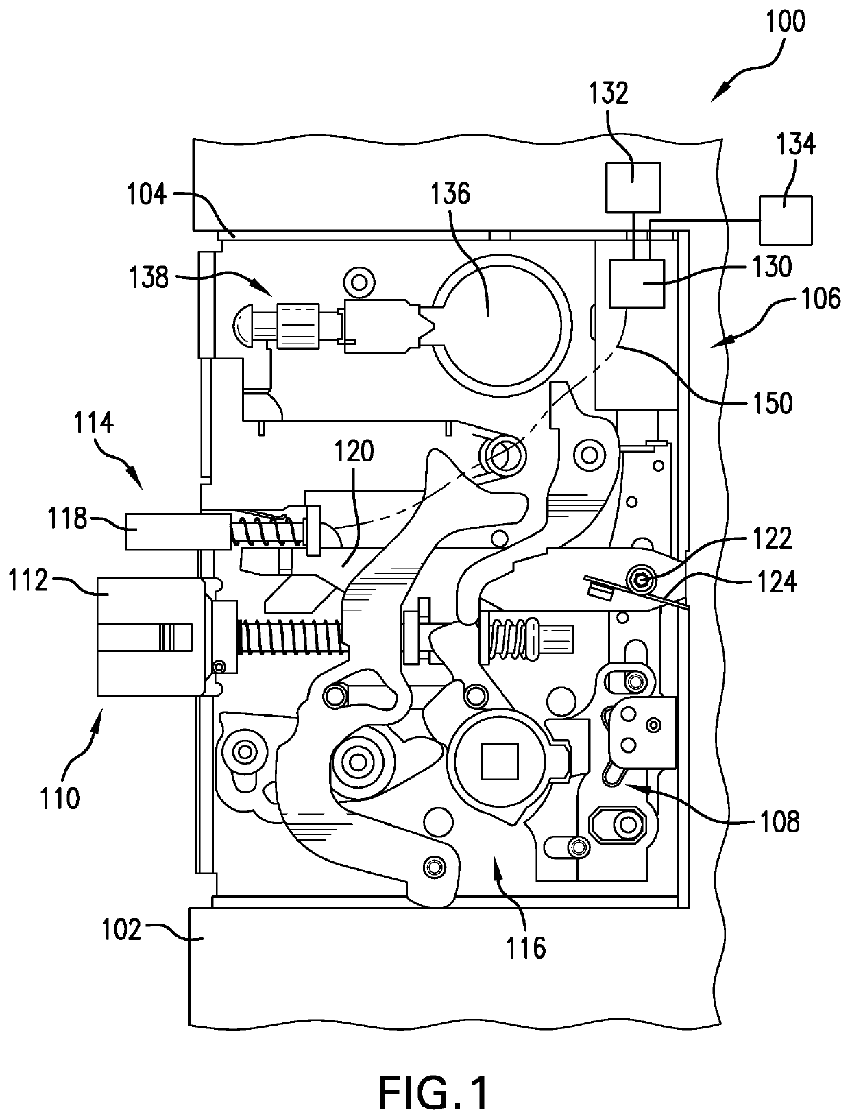
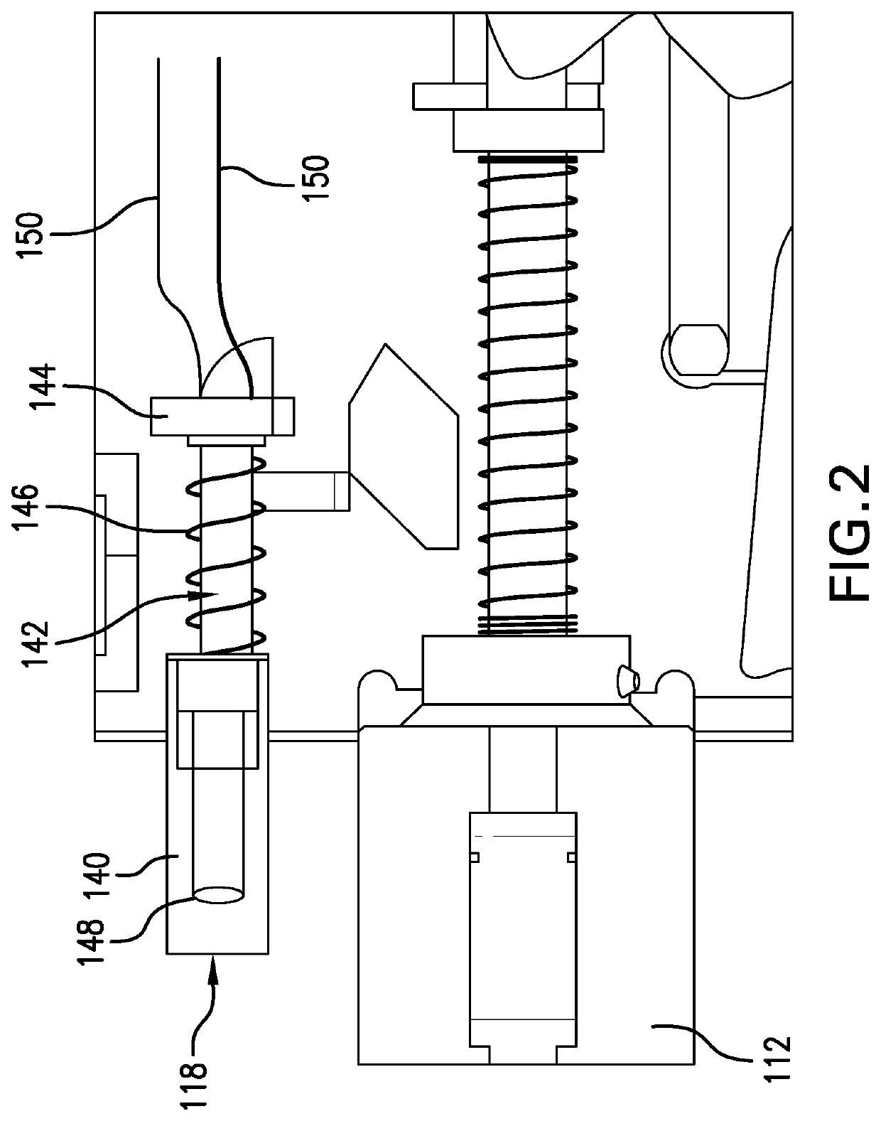
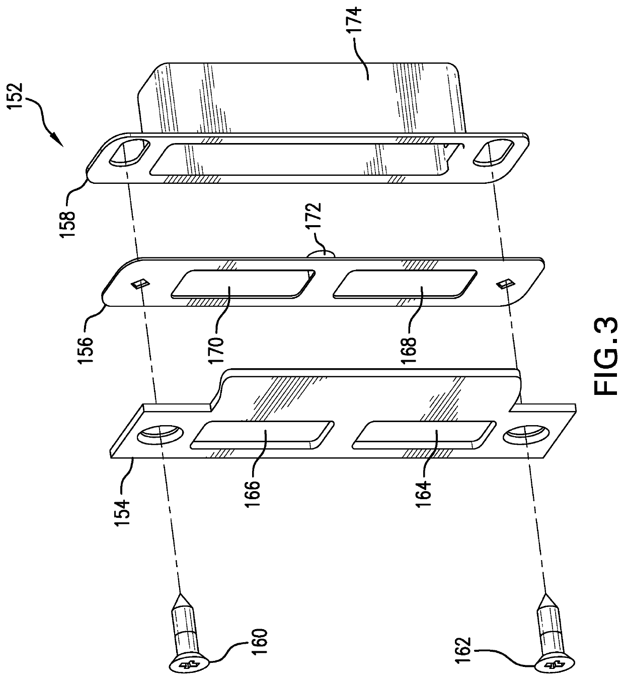
Door position sensor for mortise locks utilizing existing auxiliary or main latch operation
a technology of position sensor and mortise lock, which is applied in the direction of latching locks, building locks, constructions, etc., can solve the problems of not being able to accurately indicate, not being able to detect the magnetic field generated, and a significant amount of metal in the mortise lock assembly, so as to increase the amount of metal
- Summary
- Abstract
- Description
- Claims
- Application Information
AI Technical Summary
Benefits of technology
Problems solved by technology
Method used
Image

Examples
Embodiment Construction
[0019]The following Detailed Description refers to accompanying drawings to illustrate exemplary embodiments consistent with the present disclosure. References in the Detailed Description to “one exemplary embodiment,” an “exemplary embodiment,” an “example exemplary embodiment,” etc., indicate the exemplary embodiment described may include a particular feature, structure, or characteristic, but every exemplary embodiment may not necessarily include the particular feature, structure, or characteristic. Moreover, such phrases are not necessarily referring to the same exemplary embodiment. Further, when a particular feature, structure, or characteristic may be described in connection with an exemplary embodiment, it is within the knowledge of those skilled in the art(s) to effect such feature, structure, or characteristic in connection with other exemplary embodiments whether or not explicitly described.
[0020]The exemplary embodiments described herein are provided for illustrative pur...
PUM
 Abstract
Description
Claims
Application Information