Method and system for validating the phase of a vehicle engine

a vehicle engine and phase validation technology, applied in the direction of machines/engines, valve arrangements, electrical control, etc., can solve the problems of increasing the pollution emitted by the vehicle, unable to determine the configuration of the engine, damage the engine or the exhaust system, etc., to achieve simple, reliable and effective effects

Active Publication Date: 2021-11-23
VITESCO TECH GERMANY GMBH
View PDF17 Cites 0 Cited by
  • Summary
  • Abstract
  • Description
  • Claims
  • Application Information

AI Technical Summary

Benefits of technology

[0016]The invention therefore aims to overcome these drawbacks by proposing a simple, reliable and effective solution for determining the position of the crankshaft of a motor vehicle engine, in particular in the absence or upon failure of a camshaft sensor.
[0017]The invention aims in particular both to reduce the level of pollution of the engine and to avoid damaging the engine or the exhaust system of the vehicle.
[0025]The method according to the invention advantageously makes it possible to determine the position of the crankshaft without injecting fuel into the combustion chambers, thus making it possible to limit the deterioration of the engine and to reduce the polluting emissions from the vehicle.
[0036]According to one feature of the invention, as said at least one piston of the injection pump pumps fuel an odd number of times during one revolution of said at least one camshaft, each cam of said camshaft comprises an odd number of lobes. Thus, for one revolution of a camshaft (i.e. one engine cycle), the injection pump comprises an odd number of intake phases and an odd number of injection phases, making it possible to ensure detection of the first or second revolution of the crankshaft depending on whether the injection pump is in an intake phase or an injection phase after detection of the reference position.
[0062]According to one feature of the invention, as said at least one piston of the injection pump pumps fuel an odd number of times during one revolution of said at least one camshaft, each cam of said camshaft comprises an odd number of lobes. Thus, for one revolution of a camshaft (i.e. one engine cycle), the injection pump comprises an odd number of intake phases and an odd number of injection phases, making it possible to ensure detection of the first or second revolution of the crankshaft depending on whether the injection pump is in an intake phase or an injection phase after detection of the reference position.

Problems solved by technology

However, in the absence of a camshaft sensor or in the event of a camshaft sensor failure, it is not possible to determine the configuration of the engine and therefore to inject the fuel at the right times into the cylinders.
However, such a method has the major drawback of requiring injection of fuel into the cylinders, which can significantly increase the pollution emitted by the vehicle, or even damage the engine or the exhaust system when the injection is carried out while the exhaust valve is open.

Method used


Image

  • Method and system for validating the phase of a vehicle engine
  • Method and system for validating the phase of a vehicle engine
  • Method and system for validating the phase of a vehicle engine

Examples


Embodiment Construction

[0073]The invention will be presented below for the purpose of implementation in a motor vehicle. However, any implementation in a different context, in particular for any vehicle comprising a combustion engine whose configuration it is necessary to determine is also covered by the invention. Likewise, the invention will be described with the aid of an example in which the injection of fuel into a combustion chamber is synchronized with the opening of the intake valve connected to this same intake chamber, that is to say during the intake phase of this combustion chamber; however, such synchronization could also be carried out during another operating phase, depending on the type of engine concerned.

[0074]1 / System

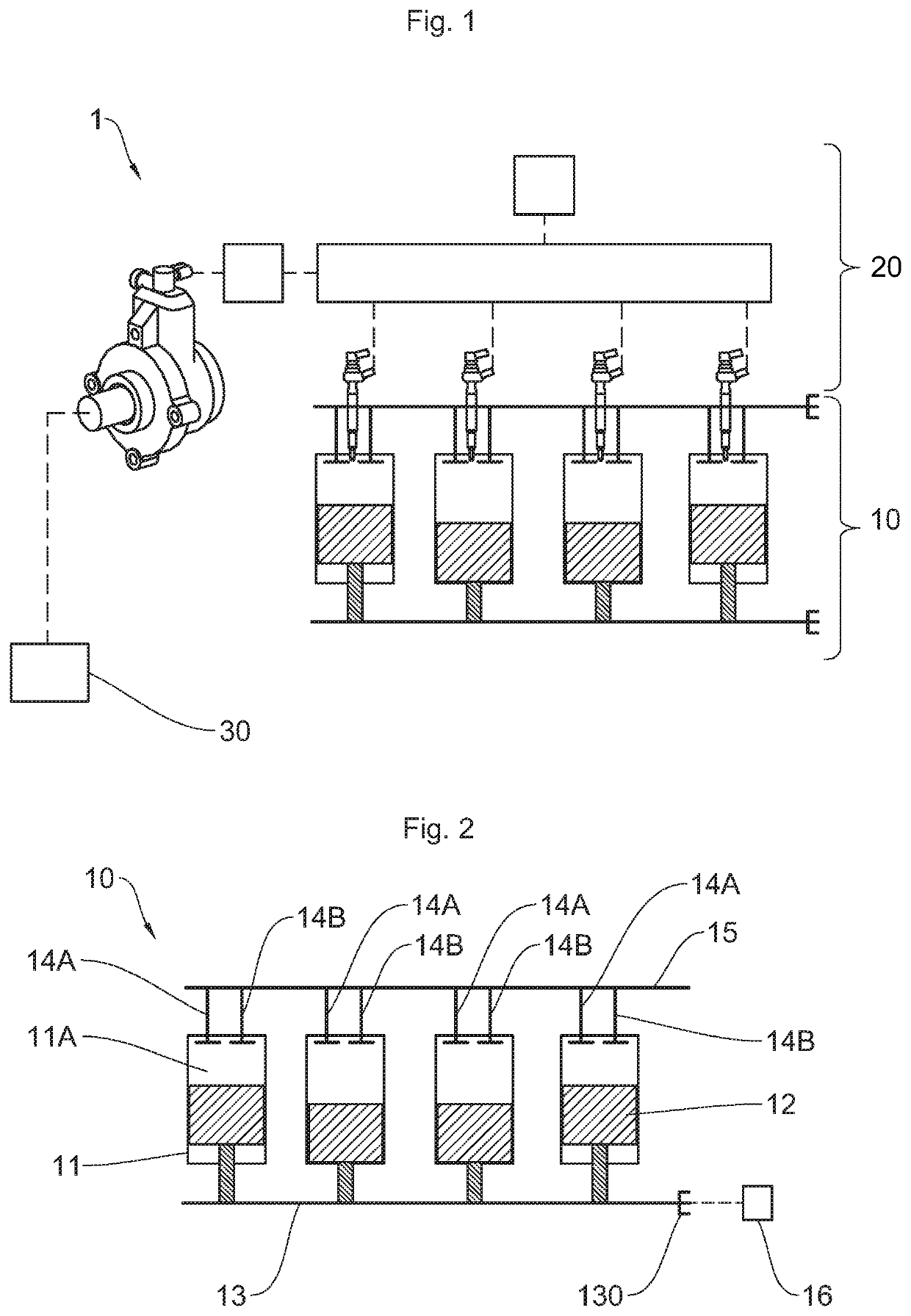
[0075]With reference to FIG. 1, the system 1, according to one form of representation of the invention, comprises a motor vehicle combustion engine 10, an injection module 20 and a control module for controlling the injection module 20, in this case in the form of a compute...


PUM


Abstract

Disclosed is a method for determining the configuration of a combustion engine of a motor vehicle including a step of detecting the reference position of the crankshaft, a step of controlling the control valve of the injection pump, after a predetermined time interval, a step of measuring a fuel pressure value in the injection rail, and a step of determining a first configuration of the engine when the fuel pressure value measured in the injection rail is greater than or equal to a first predetermined pressure threshold or determining a second configuration of the engine when the fuel pressure value measured in the injection rail is between a second predetermined pressure threshold and a third predetermined pressure threshold.

Description

BACKGROUND OF THE INVENTIONField of the Invention[0001]The invention relates to the field of synchronization of a combustion engine and relates more specifically to a method and a system for determining the position of a crankshaft of a combustion engine in order to inject fuel into the cylinders as a function of the position of the camshaft.[0002]The invention aims in particular to determine the configuration in which a combustion engine is by determining the position of the crankshaft of said engine without injecting fuel into the engine cylinders, in order to reduce the level of polluting emissions.Description of the Related Art[0003]As is known, a combustion engine of a motor vehicle comprises hollow cylinders each delimiting a combustion chamber into which a mixture of air and fuel is injected. This mixture is compressed in the cylinder by a piston and ignited so as to make the piston move in translation inside the cylinder. The movement of the pistons in each cylinder of the e...

Claims


Application Information

Patent Timeline
Patent Type & Authority Patents(United States)
IPC IPC(8): F02D41/00F02D41/06F02D41/38
CPCF02D41/009F02D41/062F01L2820/041F02D41/3845F02D2041/0092F02D2200/0602
Inventor AGNUS, YVESLEFEVRE, JULIEN
Owner VITESCO TECH GERMANY GMBH
Why Eureka
Try Eureka