Method for managing a piston pump for a heat engine

a technology of heat engine and piston pump, which is applied in the direction of positive displacement liquid engine, electric control, machines/engines, etc., can solve the problems of increased system footprint and complexity, noise disturbance, and the inability to control the internal pressure of the piston pump, so as to reduce the noise generated by the piston pump. , the effect of simple structur

Active Publication Date: 2022-03-24
VITESCO TECH GERMANY GMBH
View PDF12 Cites 0 Cited by
  • Summary
  • Abstract
  • Description
  • Claims
  • Application Information

AI Technical Summary

Benefits of technology

[0009]The present invention aims to propose a simple, reliable and effective solution for limiting the noise generated by a piston pump.

Problems solved by technology

However, the use of a pump and an external pressure regulator increases the footprint and complexity of the system.
However, such a piston pump with internal pressure regulation also has its drawbacks.
When the solenoid controls the movement of the piston, the piston moves rapidly to its high position in which it strikes the core of the solenoid, generating noise disturbance.
In addition, in certain conditions, particularly during the engine starting phase, the fuel pressure between the pump and the engine is low.
Also, during the operation of the pump, the low fuel pressure at the outlet of the pump offers little or no resistance to the return spring, which then moves the piston rapidly to its low position in which it strikes the bottom of the cylinder, which likewise generates noise disturbance.
In other words, in this case, the piston generates noise by striking the solenoid in the high position and striking the cylinder in the low position until pressure is established between the engine and the pump.
In particular, in the starting phase of the vehicle, during which the pump operates to pressurize the fuel when the combustion engine has not yet started, as there is no engine noise, the noise of the pump then becomes particularly audible, notably for individuals in the vehicle or around the vehicle, which presents a drawback.
In addition, as this phase can be relatively long, the noise disturbance remains audible for a significant length of time, which therefore presents a major drawback.

Method used


Image

  • Method for managing a piston pump for a heat engine
  • Method for managing a piston pump for a heat engine
  • Method for managing a piston pump for a heat engine

Examples


Embodiment Construction

[0029]The method according to the invention is intended to be implemented in a vehicle with a combustion engine in order to control a piston pump of said vehicle. The term “vehicle” is given in particular to mean a motor vehicle and a motorcycle (particularly having a cylinder capacity of less than 125 cm3), but also devices with a small cylinder-capacity combustion engine such as, for example, a lawnmower.

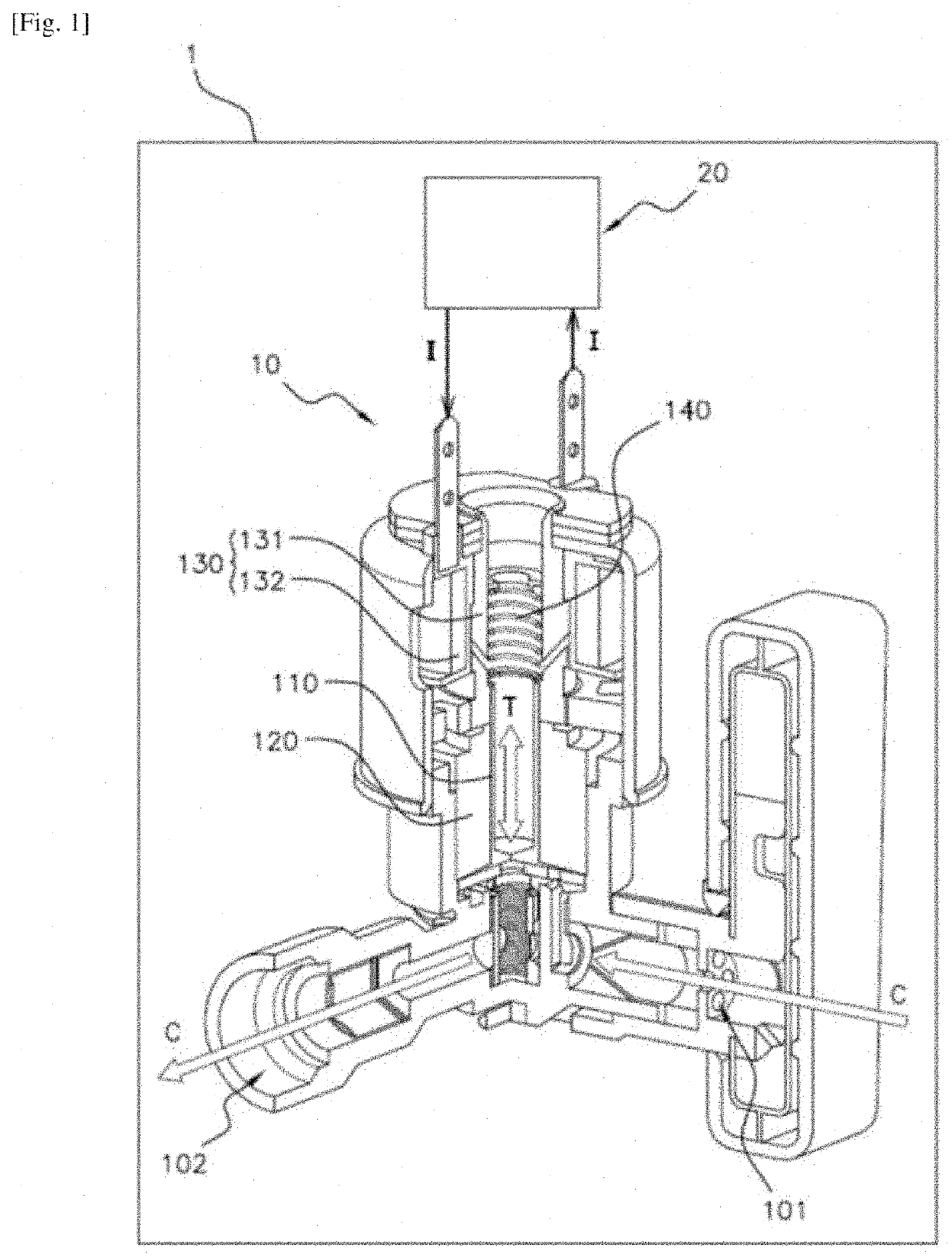
[0030]FIG. 1 schematically shows one example of a vehicle 1 comprising a piston 110 pump 10 and a computer 20 for controlling the pump 10.

[0031]The vehicle 1, such as a motorcycle or a lawnmower, comprises a combustion engine (not shown) supplied with fuel C by a fuel tank (not shown). The combustion engine comprises a plurality of cylinders each defining a combustion chamber into which a volume of fuel C and a volume of air are introduced on each cycle of the engine in order to combust the mixture thereof.

[0032]Each cylinder comprises a piston mounted in the combustion chamber. T...


PUM


Abstract

Disclosed is a method for managing a piston pump using a computer of a vehicle, the pump including a guide, a piston slidably mounted in the guide, and a solenoid, suitable for moving the piston, the method including, as long as the fuel pressure in the compression chamber of the pump is below a predetermined pressure threshold, a step of the computer controlling the solenoid in order to move the piston to its high position, and a step of the computer detecting that the predetermined pressure threshold has been exceeded when the current value, measured after a predetermined period, is greater than or equal to a predetermined reference value so that the computer ceases to control the solenoid.

Description

CROSS-REFERENCE TO RELATED APPLICATIONS[0001]This application is the U.S. national phase of International Application No. PCT / EP2020 / 051577 filed Jan. 23, 2020 which designated the U.S. and claims priority to French Application No. 1900607 filed Jan. 24, 2019, the entire contents of each of which are hereby incorporated by reference.BACKGROUND OF THE INVENTIONField of the Invention[0002]The invention relates to the field of the injection of fuel into a combustion engine and relates more particularly to a method for managing a fuel injection pump. The invention applies more particularly to small cylinder-capacity combustion engines such as, for example, motorcycle engines with a cylinder capacity of less than 125 cm3, or lawnmower engines.Description of the Related Art[0003]As is known, the injection of fuel into a cylinder of a combustion engine is performed using a pump. In the case of small cylinder-capacity engines, for example motorcycle or lawnmower engines with a cylinder capa...

Claims


Application Information

Patent Timeline
Patent Type & Authority Applications(United States)
IPC IPC(8): F02D41/30F02M51/04F02M59/02F02M59/10F04B17/04F04B49/02F04B49/06F04B49/08F02D41/06F02M37/08
CPCF02D41/3082F02M51/04F02M59/025F02M59/10F04B17/04F04B2203/0401F04B49/065F04B49/08F02D41/062F02M37/08F04B49/022F04B49/06F02M2037/085
Inventor MOINE, XAVIER
Owner VITESCO TECH GERMANY GMBH
Why Eureka
Try Eureka