Thermal deflection apparatus

a deflection apparatus and heat dissipation technology, applied in the direction of gearing details, belts/chains/gear parts, gear lubrication/cooling, etc., can solve the problems of affecting the operation, performance or durability of other nearby components, ptu deformation, and inefficiency, so as to reduce the transfer of heat from other engine components.

Active Publication Date: 2021-11-23
RB DISTRIBUTION INC A PENNSYLVANIA CORP
View PDF10 Cites 0 Cited by
  • Summary
  • Abstract
  • Description
  • Claims
  • Application Information

AI Technical Summary

Problems solved by technology

Engines can have one or more components that generate excessive amounts of heat during operation.
That heat can affect the operation, performance, or durability of other nearby components.
As a result, heat from the exhaust pipe will heat the PTU, which can cause the PTU to degrade and not work as efficiently.
For instance, excessive heat can cause expansion in the bearings and gear bindings, resulting in catastrophic failure of the PTU.
And, can cause degradation of the PTU lubrication resulting in bearing and gear binding, and also resulting in catastrophic failure of the PTU.

Method used


Image

  • Thermal deflection apparatus
  • Thermal deflection apparatus
  • Thermal deflection apparatus

Examples


Embodiment Construction

[0016]In describing the illustrative, non-limiting embodiments of the invention illustrated in the drawings, specific terminology will be resorted to for the sake of clarity. However, the invention is not intended to be limited to the specific terms so selected, and it is to be understood that each specific term includes all technical equivalents that operate in similar manner to accomplish a similar purpose. Several embodiments of the invention are described for illustrative purposes, it being understood that the invention may be embodied in other forms not specifically shown in the drawings.

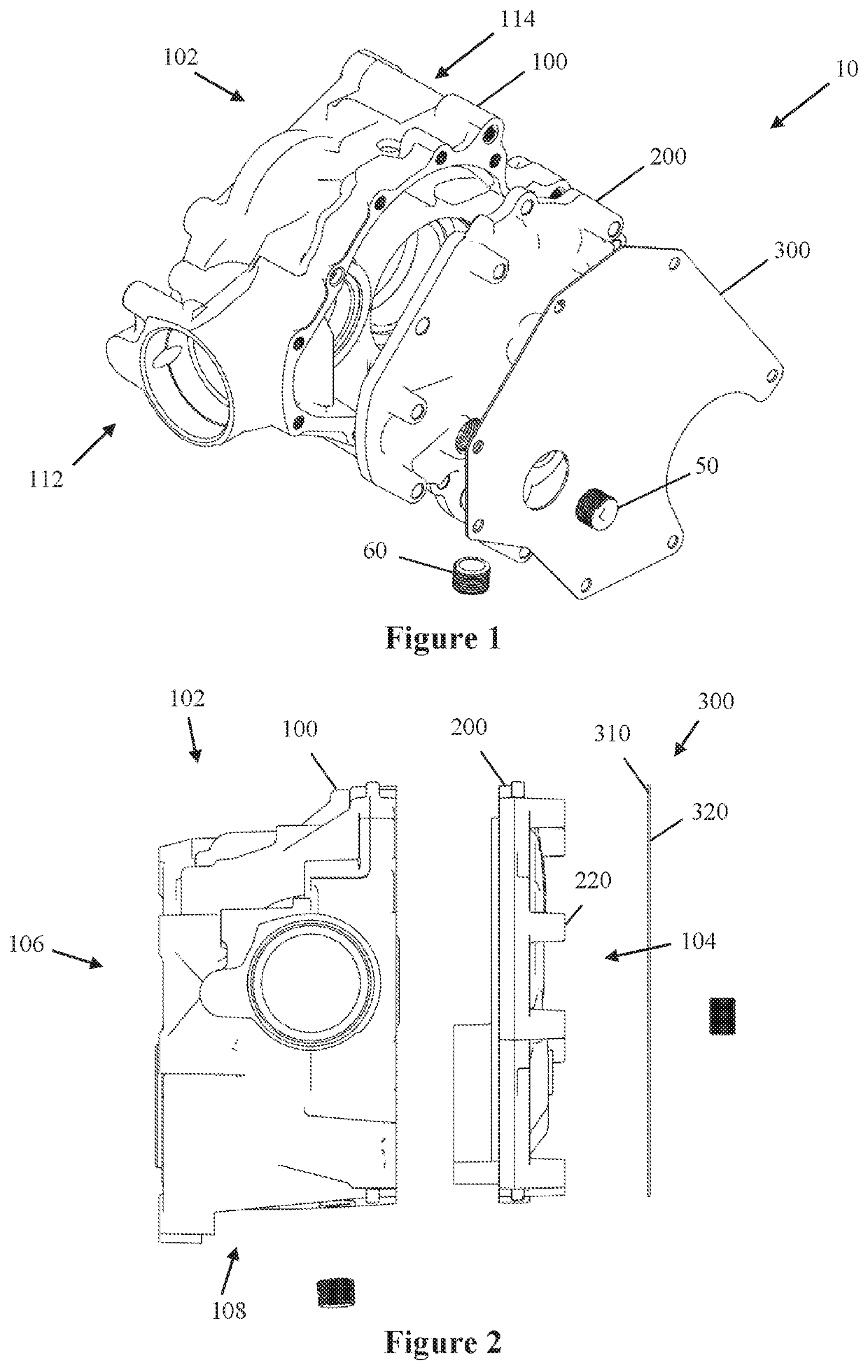
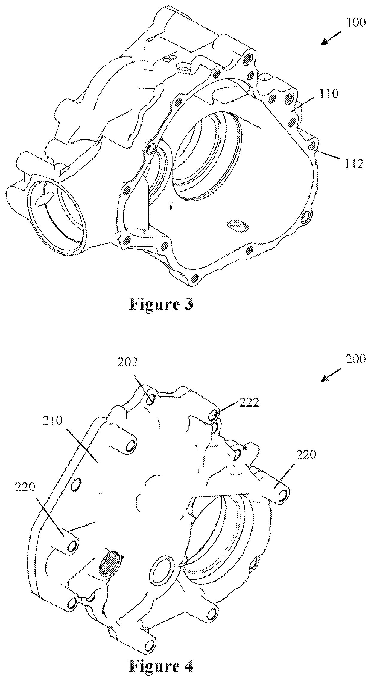
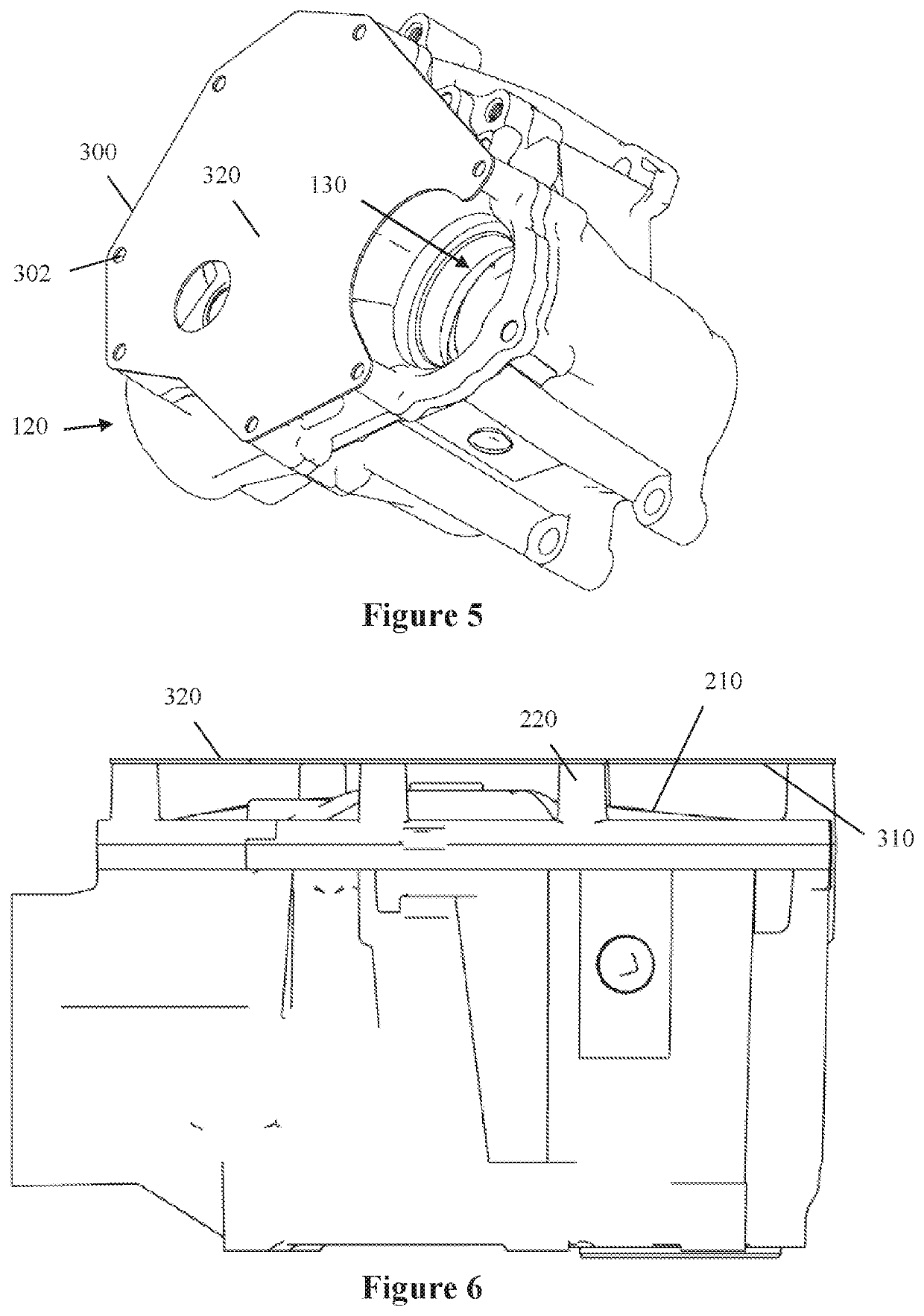
[0017]Turning to the drawings, FIGS. 1, 2 show a PTU assembly 10 in accordance with one embodiment of the invention. The assembly 10 includes a PTU housing 100, PTU face plate 200 and a thermal deflection apparatus or heat shield 300. The PTU face plate 200 attaches to the PTU housing 100. One or more mounting holes can be provided in the housing 100 and / or the face plate 200 to mount the housi...


PUM

PropertyMeasurementUnit
temperaturesaaaaaaaaaa
sizeaaaaaaaaaa
lengthaaaaaaaaaa

Abstract

A Power Transfer Unit (PTU) has a housing with at least one side having an outer surface. One or more standoffs are provided at the at least one side of the housing and extend outward from the outer surface of the housing. A thermal deflector formed as a flat plate is attached to the standoffs at a predetermined distance from the outer surface of the housing. The flat plate deflects heat from nearby components, such as the catalytic converter and / or exhaust pipe, away from the PTU.

Description

BACKGROUND OF THE INVENTIONField of the Invention[0001]The present invention relates to a thermal deflection apparatus. More particularly, the present invention relates to a heat shield for an engine component or part and especially for a Power Transfer Unit.BACKGROUND OF THE RELATED ART[0002]Engines can have one or more components that generate excessive amounts of heat during operation. That heat can affect the operation, performance, or durability of other nearby components. For instance, the catalytic converter needs to operate at high temperatures of approximately 800 degrees Fahrenheit to operate properly. An exhaust pipe carries emissions from the catalytic converter, which is typically located close to the engine, to be exhausted at the rear of the vehicle. The emissions carried by the exhaust pipe are heated, which in turn heats the exhibit pipe. The catalytic converter and / or the exhaust pipe can be in close proximity to other engine components.[0003]A Power Transfer Unit ...

Claims


Application Information

Patent Timeline
Patent Type & Authority Patents(United States)
IPC IPC(8): F16H57/04F16H57/032
CPCF16H57/0419F16H57/032F16H2057/02043
Inventor LEICHLITER, CHAD TIMOTHYBUTCHER, STEVEN WILLIAM
Owner RB DISTRIBUTION INC A PENNSYLVANIA CORP
Why Eureka
Try Eureka