Operating Method for a Motor Vehicle Diesel Engine Having an Exhaust Emission Control System

Inactive Publication Date: 2014-02-13
DAIMLER AG
View PDF3 Cites 30 Cited by
  • Summary
  • Abstract
  • Description
  • Claims
  • Application Information

AI Technical Summary

Benefits of technology

[0018]The heating up of the exhaust emission control system may be further accelerated when, in another embodiment of the invention, in the first operating range an electric heating element connected upstream from the three-way catalytic converter is energized within a second temperature range for the three-way catalytic converter. A preferred suitable heating element is a so-called E-catalytic converter, which as a disk-shaped, optionally catalytically coated, electrically heatable metal support element is conn

Problems solved by technology

This has proven to be difficult, in particular for an exhaust emission control system that is comparatively slightly heated, since lambda sensors which are often used for this

Method used


Image

  • Operating Method for a Motor Vehicle Diesel Engine Having an Exhaust Emission Control System
  • Operating Method for a Motor Vehicle Diesel Engine Having an Exhaust Emission Control System
  • Operating Method for a Motor Vehicle Diesel Engine Having an Exhaust Emission Control System

Examples


Embodiment Construction

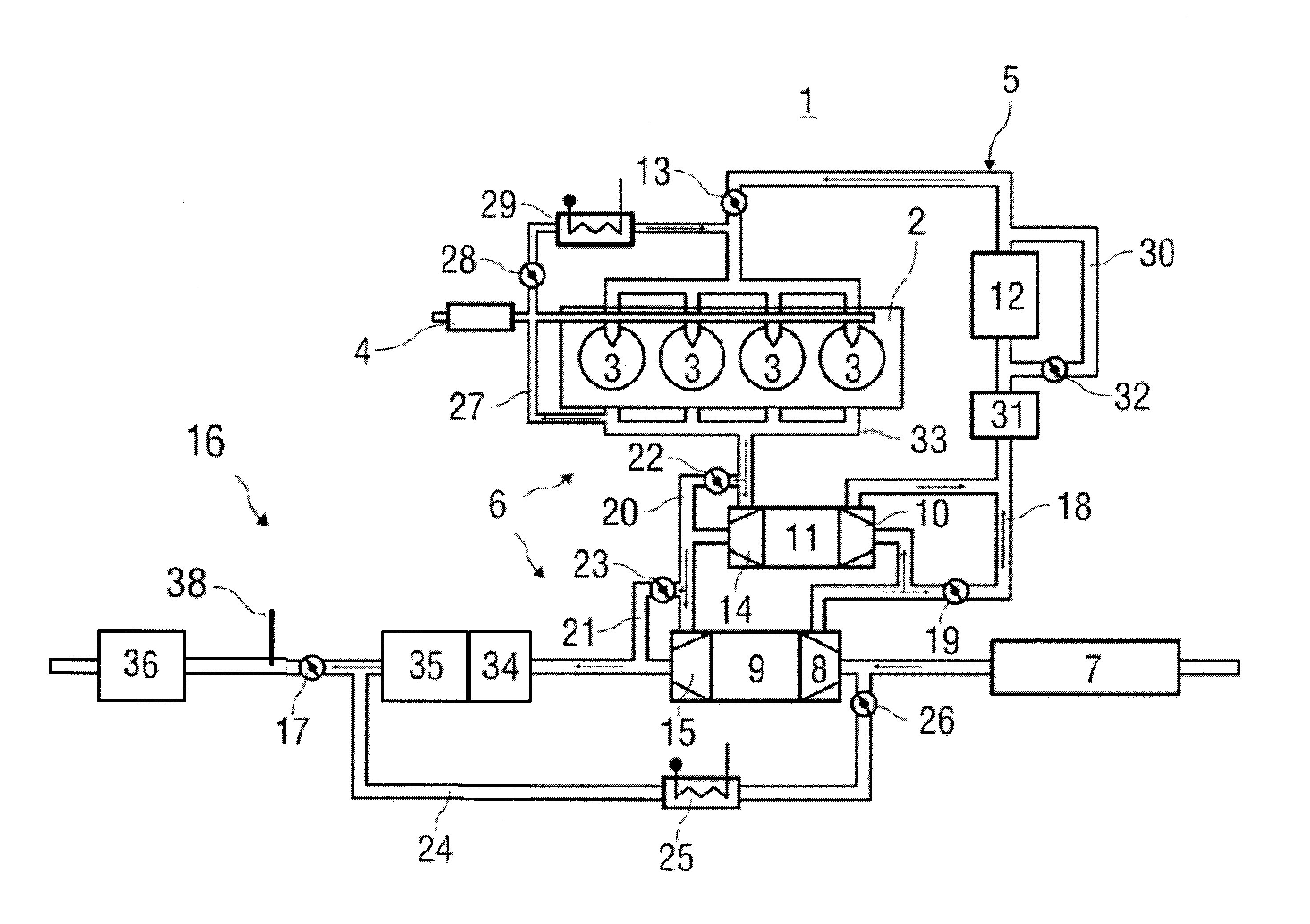
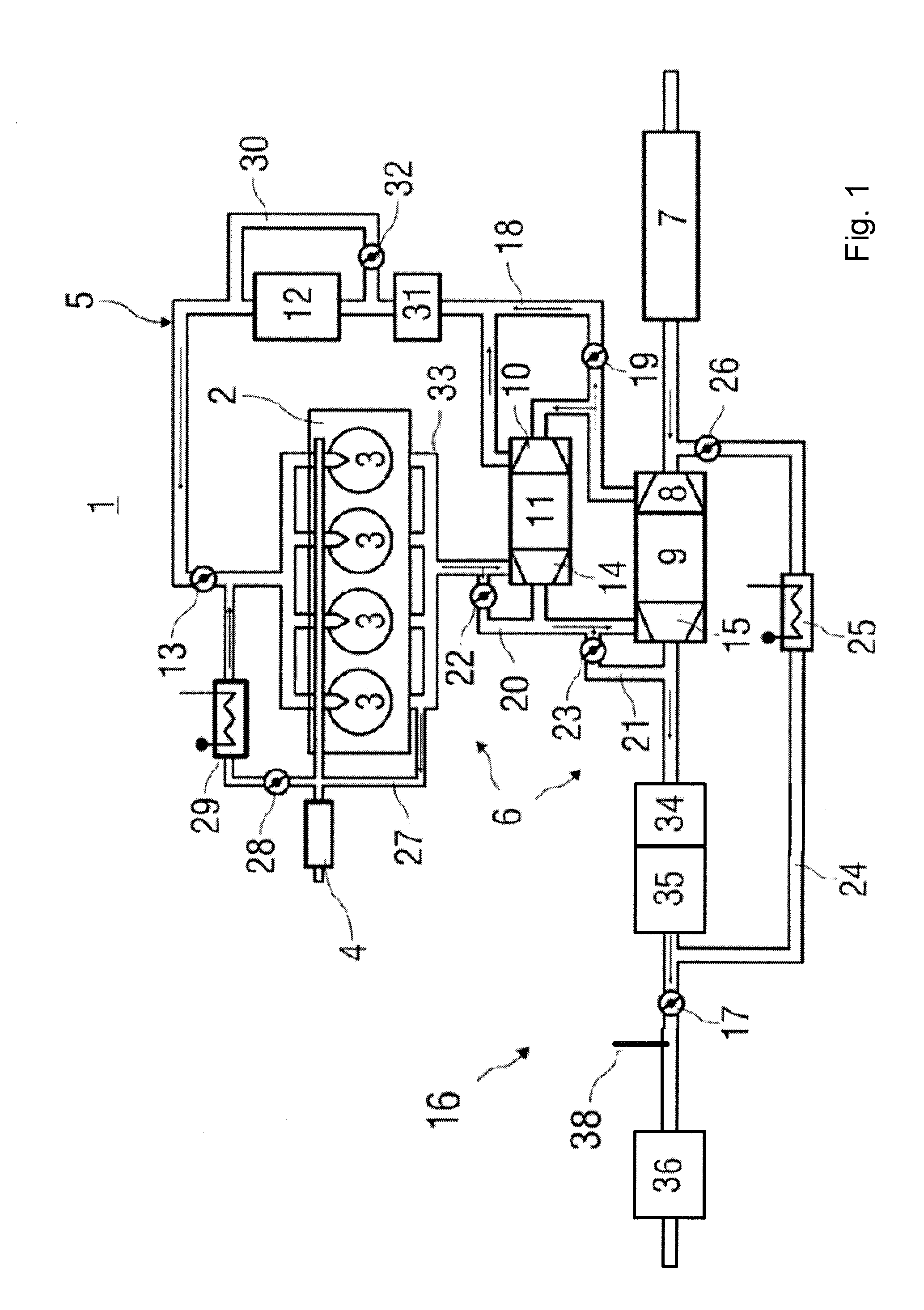
[0024]FIG. 1 shows a schematic diagram of one advantageous embodiment of a motor vehicle diesel engine 1 having a connected exhaust emission control system in which the method explained in greater detail below may be used. In the present case, the diesel engine 1 has two-stage supercharging and two-stage exhaust gas recirculation, and includes an engine block 2 having working cylinders 3 with combustion chambers (not further identified), the working cylinders 3 and their respective combustion chambers can be supplied with fuel by means of a high-pressure pump 4. The working cylinders 3 and their respective combustion chambers may be supplied with combustion air via an air supply system 5, and exhaust gas may be discharged from the working cylinders 3 via an exhaust tract 6. An air filter 7, a first compressor 10 of a first exhaust gas turbocharger designed as a high-pressure exhaust gas turbocharger 11, a second compressor 8 of a second exhaust gas turbocharger designed as a low-pre...


PUM


Abstract

An operating method is provided for a motor vehicle diesel engine having an exhaust emission control system that includes a three-way catalytic converter and an SCR catalytic converter situated one behind the other in the flow direction of the exhaust gas. The diesel engine is operated, at least intermittently, with an air-fuel ratio of approximately λ=1.0 in a first operating range in which the SCR catalytic converter falls below a predefinable minimum temperature and with excess air that is typical for normal diesel engine operation in a second operating range in which the SCR catalytic converter exceeds the predefinable minimum temperature. An output signal of an exhaust gas sensor situated downstream from the three-way catalytic converter and which is correlated with a NOx concentration of the exhaust gas is used to set the air-fuel ratio in the first operating range.

Description

BACKGROUND AND SUMMARY OF THE INVENTION[0001]Exemplary embodiments of the present invention relate to an operating method for a motor vehicle diesel engine having an exhaust emission control system, comprising a three-way catalytic converter and an SCR catalytic converter situated one behind the other in the flow direction of the exhaust gas, in which the diesel engine is operated, at least intermittently, with an air-fuel ratio of approximately λ=1.0 in a first operating range during which the SCR catalytic converter falls below a predefinable minimum temperature, and is operated with excess air that is typical for normal diesel engine operation in a second operating range during which the SCR catalytic converter exceeds the predefinable minimum temperature.[0002]German patent document DE 10 2009 015 900 A1 discloses a generic operating method but does not mention how the stoichiometric air-fuel ratio of approximately λ=1.0, which is atypical for diesel engine operation, is set. Th...

Claims


Application Information

Patent Timeline
IPC IPC(8): F01N3/10
CPCF01N3/10F01N3/035F01N3/101F01N3/2013F01N3/208F01N2240/16F01N2430/085F01N2560/026F01N2610/02F01N2900/0412F01N2900/1402F02B29/0418F02B37/013F02D23/02F02D41/0235F02D41/024F02D41/029F02D41/1461F02D2200/0802F01N13/0097F01N13/009F02M26/05F02M26/06F02M26/08F02M26/10F02M26/15F02M26/24Y02A50/20Y02T10/12
Inventor BALTHES, ORTWINKEPPELER, BERTHOLDMUELLER, SIEGFRIED
Owner DAIMLER AG
Why Eureka
Try Eureka