Striking tool and rotor fitted therewith for a machine for crushing metal objects or stone materials

Active Publication Date: 2021-12-14
AUGUST THYSSEN HUETTE AG
View PDF25 Cites 0 Cited by
  • Summary
  • Abstract
  • Description
  • Claims
  • Application Information

AI Technical Summary

Benefits of technology

The invention is a striking tool with an extended bearing opening that absorbs dynamic loads during use, reducing the risk of crack formation and breakage. The tool has a constricted portion between its bearing section and striking section, and the radius of the extension section is smaller than the support section to achieve a uniform thickness profile. The extension section also has at least two lower sections that serve as additional support sections for the tool. These sections delimit a space between them that is laterally separated from the material of the bearing section to further increase the effect of extending the dynamic load-absorbing region.

Problems solved by technology

The centrifugal forces acting as a function of the respective revolution speeds in the case of the striking tools of the above-mentioned type mounted so as to rotate vertically or horizontally are high and lead to strong dynamic loads of the region of the bearing section which surrounds the bearing opening.
Practical experience shows that, in spite of this setting of the toughness of the bearing section of the striking tools that is tried and tested in practice, damage results due to excessive loads.
Thus, cracks appear in the regions of the bearing section surrounding the bearing opening, which can lead to breakage.

Method used


Image

  • Striking tool and rotor fitted therewith for a machine for crushing metal objects or stone materials
  • Striking tool and rotor fitted therewith for a machine for crushing metal objects or stone materials
  • Striking tool and rotor fitted therewith for a machine for crushing metal objects or stone materials

Examples


Embodiment Construction

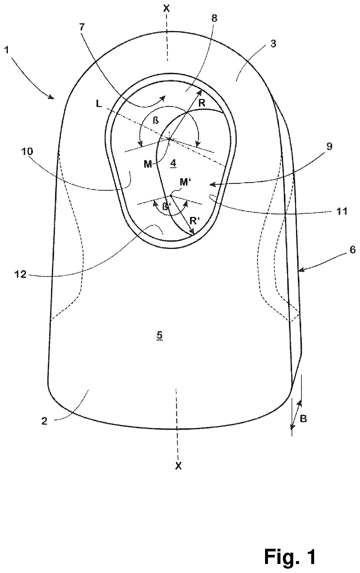
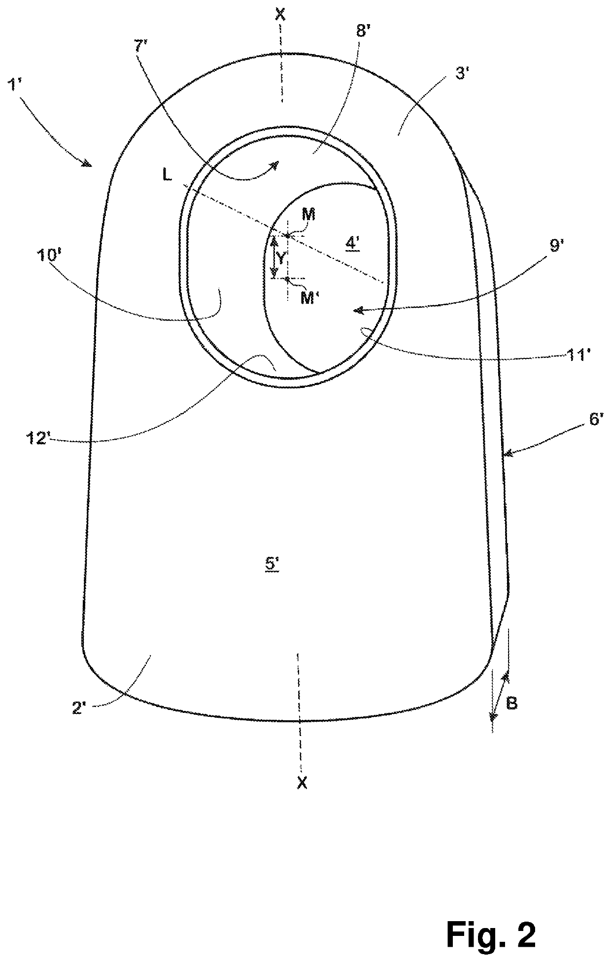
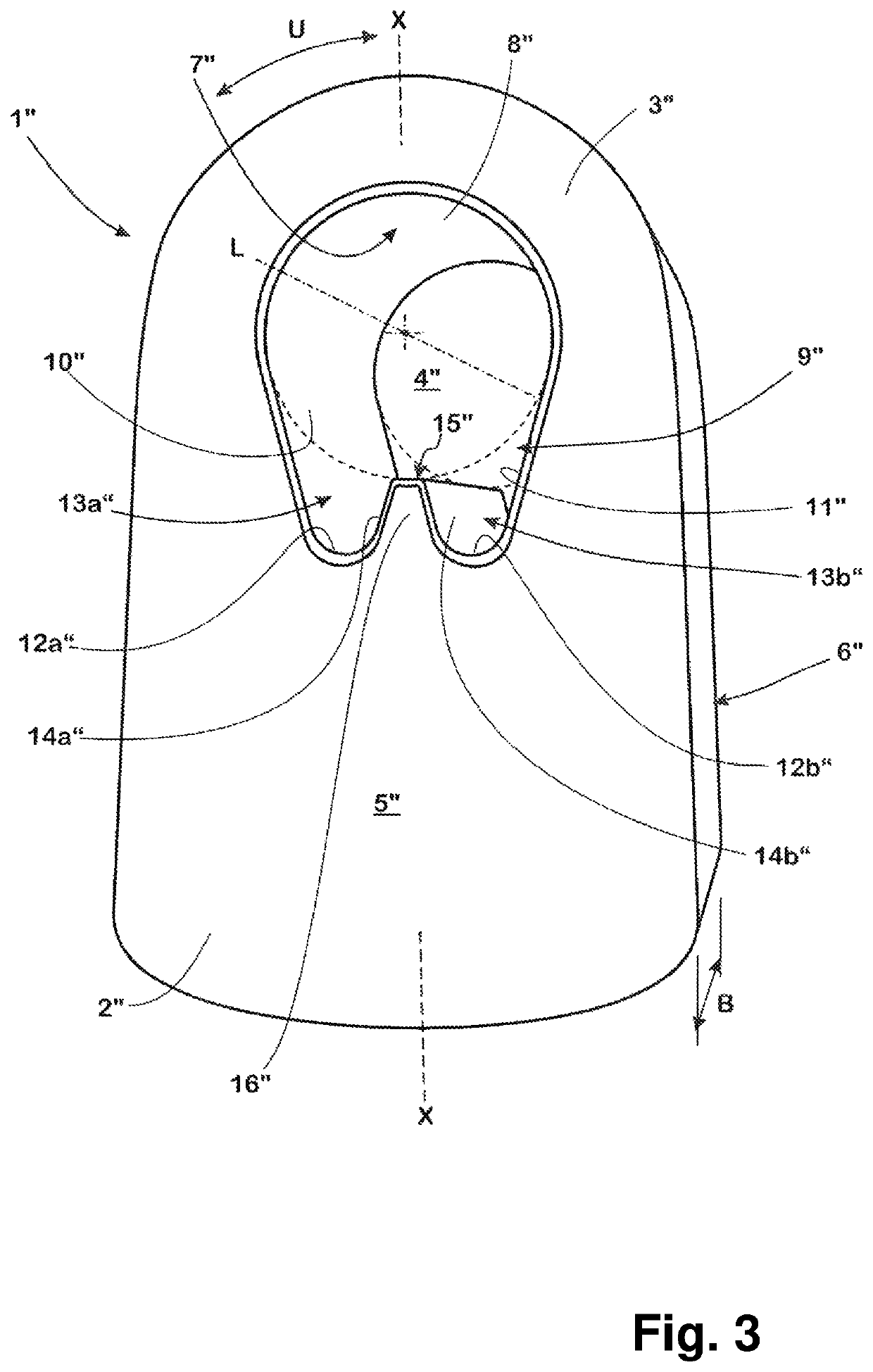
[0037]The striking tools 1, 1′, 1″ represented in FIGS. 1 to 3 serve as striking hammers for crushing metal scrap, such as vehicle bodies, mineral raw materials or mineral waste such as construction debris, overburden or the like.

[0038]To this end, the striking tools 1, 1′, 1″ are mounted on a conventional rotor not shown here in the manner so as to swing on a shaft of the rotor also not shown here. The manner of the swinging mounting of a striking tool, which belongs to the same generic group as a striking tool according to the invention, is for example described in EP 1 047 499 B1.

[0039]In order to fulfil its purpose, the striking tool 1, 1′, 1″ cast in a conventional manner in one piece for example from a Hadfield steel has a striking section 2, 2′, 2″ hardened by a suitable heat treatment in a manner also known per se, which comes into contact with the material to be crushed during practical use and as a result is exposed to extreme striking loads, and has a bearing section 3, 3...


PUM


Abstract

A striking tool for crushing metal or stone materials, where the striking tool is manufactured from an iron-based material and includes a bearing section, into which a bearing opening is formed around a pivot axis and includes a striking section which is exposed to a striking load by contact with the material to be crushed, and a rotor equipped therewith for a machine to crush metal or stone materials. The striking tool improves with the ability of its bearing section to absorb the dynamic loads acting on the striking tool. The bearing opening has a support section, on whose inner circumferential surface the striking tool is mounted for its swing movement around the pivot axis and has an extension section, which is connected to the support section and the bearing opening is extended in the direction of the striking section with respect to the support section.

Description

CROSS-REFERENCE TO RELATED APPLICATION[0001]This application is the United States national phase of International Application No. PCT / EP2018 / 059910 filed Apr. 18, 2018, the disclosure of which is hereby incorporated by reference in its entirety.BACKGROUND OF THE INVENTIONField of the Invention[0002]The invention relates to a striking tool for crushing metal objects or stone materials.Description of Related Art[0003]Such striking tools are also called striking hammers and are typically used in machines to crush metal scrap, such as bodies of vehicles intended for scrap, or demolition or construction waste.[0004]The striking tools of the type mentioned here, which are usually cast in one piece from an iron-based material from a cast metal material or, alternatively, manufactured by forging or flame cutting a correspondingly formed primary product or as a weld construction, comprise a bearing section in which a bearing opening is formed with a cylindrically shaped inner circumferential...

Claims


Application Information

Patent Timeline
IPC IPC(8): B02C13/28
CPCB02C13/28
Inventor MAYER, BRUNOMAYER, STEPHAN O.
Owner AUGUST THYSSEN HUETTE AG
Why Eureka
Try Eureka