Vehicle, vehicle control system, vehicle control method

a vehicle control system and vehicle control technology, applied in the direction of hybrid vehicles, battery/fuel cell control arrangement, transportation and packaging, etc., can solve the problems of large calculation load for conversion, inability to study the combination of power restricting battery pack and current restricting control device, and inability to adopt current restricting battery pack in a vehicle equipped with a power restricting control devi

Active Publication Date: 2021-12-14
TOYOTA JIDOSHA KK
View PDF9 Cites 3 Cited by
  • Summary
  • Abstract
  • Description
  • Claims
  • Application Information

AI Technical Summary

Benefits of technology

[0009]The present disclosure provides a vehicle, a vehicle control system, and a vehicle control method that can perform at least one of power-based input restriction and power-based output restriction on a secondary battery included in a current restricting battery pack.
[0014]According to the vehicle of the first aspect of the present disclosure, the conversion formula is selected from the options according to the situation, and the current upper limit value is converted into the power upper limit value using the selected conversion formula. Therefore, in a situation where it is required to severely control the current of the secondary battery, it is possible to enhance the controllability of the current of the secondary battery by selecting a conversion formula with high conversion accuracy. In contrast, in a situation where it is not required to severely control the current of the secondary battery, the calculation load of the converter can be reduced by using (selecting) a conversion formula with a small calculation load (that is, a conversion formula with low conversion accuracy). The options for the conversion formula can be set as desired.
[0017]On the other hand, the second conversion formula uses the first estimated voltage value to convert the first current upper limit value into the first power upper limit value. The voltage of the secondary battery changes depending on the magnitude of the current. The second conversion formula multiplies the first current upper limit value by the first estimated voltage value (that is, the voltage value of the secondary battery in the state where the current corresponding to the first current upper limit value is flowing) described above to convert the first current upper limit value into the first power upper limit value. This makes it possible to acquire the first power upper limit value corresponding to the first current upper limit value with high accuracy.
[0018]As described above, it is considered in the second conversion formula that the voltage of the secondary battery changes depending on the magnitude of the current, and the first power upper limit value corresponding to the first current upper limit value can be obtained with higher accuracy in the conversion using the second conversion formula than in the conversion using the first conversion formula. However, even in the conversion using the first conversion formula, the conversion accuracy is ensured to the extent that the current controllability of the secondary battery is not unduly hindered. In the vehicle having the above configuration, for example, when the state of the secondary battery in which it is required to severely control the current of the secondary battery is set as the first state, power-based input restriction is performed using the first power upper limit value converted with the first conversion formula in the normal state (that is, when the state of the secondary battery is not included in the first state), whereby the calculation load of the converter is reduced. On the other hand, in a situation where it is required to severely control the current of the secondary battery (that is, when the state of the secondary battery is included in the first state), power-based input restriction is performed using the first power upper limit value converted with the second conversion formula, whereby the controllability of the input current of the secondary battery can be improved.
[0020]The third conversion formula uses the measured value of the voltage of the secondary battery to convert the second current upper limit value into the second power upper limit value. Since the third conversion formula uses the measured value of the voltage as it is, the second current upper limit value can be converted into the second power upper limit value without performing a complicated calculation. The fourth conversion formula uses the voltage value of the secondary battery in the state where the current corresponding to the second current upper limit value is flowing (that is, the second estimated voltage value) to convert the second current upper limit value into the second power upper limit value. Like the above-mentioned second conversion formula, it is considered in the fourth conversion formula that the voltage of the secondary battery changes depending on the magnitude of the current, and the second power upper limit value corresponding to the second current upper limit value can be obtained with higher accuracy in the conversion using the fourth conversion formula than in the conversion using the third conversion formula. However, even in the conversion using the third conversion formula, the conversion accuracy is ensured to the extent that the current controllability of the secondary battery is not unduly hindered. According to the vehicle of the first aspect of the present disclosure, for example, when the state of the secondary battery in which it is required to severely control the current of the secondary battery is set as the second state, power-based output restriction is performed using the second power upper limit value converted with the third conversion formula in the normal state (that is, when the state of the secondary battery is not included in the second state), whereby the calculation load of the converter is reduced. On the other hand, in a situation where it is required to severely control the current of the secondary battery (that is, when the state of the secondary battery is included in the second state), power-based output restriction is performed using the second power upper limit value converted with the fourth conversion formula, whereby the controllability of the output current of the secondary battery can be improved.

Problems solved by technology

However, it has not been expected to use a current restricting battery pack and a power restricting control device in combination, so no study has been conducted on means for using a current restricting battery pack and a power restricting control device in combination.
Thus, it is difficult to adopt a current restricting battery pack in a vehicle equipped with a power restricting control device.
On the other hand, however, the calculation load for conversion tends to be larger as the conversion accuracy of the conversion formula becomes higher.

Method used


Image

  • Vehicle, vehicle control system, vehicle control method
  • Vehicle, vehicle control system, vehicle control method
  • Vehicle, vehicle control system, vehicle control method

Examples


Embodiment Construction

[0053]Embodiments of the present disclosure will be described in detail with reference to the drawings. It should be noted that the same or corresponding parts in the drawings are denoted by the same reference characters and repetitive description thereof will be omitted. Hereinafter, an electronic control unit is also referred to as “ECU”.

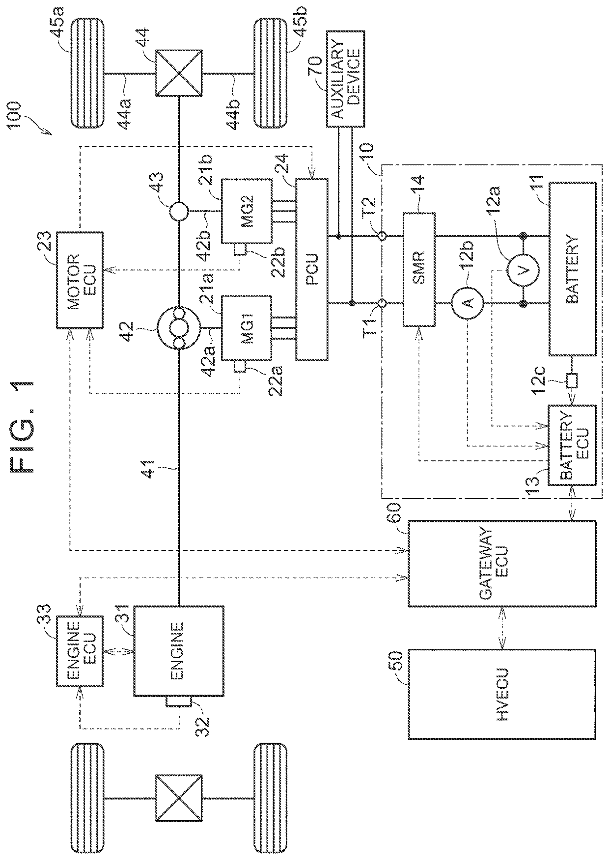
[0054]FIG. 1 is a diagram showing a configuration of a vehicle according to the present embodiment. In the present embodiment, a front-wheel drive four-wheel vehicle (more specifically, a hybrid vehicle) is assumed to be used, but the number of wheels and the drive system can be changed as appropriate. For example, the drive system may be four-wheel drive.

[0055]Referring to FIG. 1, the vehicle 100 is equipped with a battery pack 10 including a battery ECU 13. Further, a motor ECU 23, an engine ECU 33, an HV ECU 50, and a gateway ECU 60 are mounted on the vehicle 100 separately from the battery pack 10. The motor ECU 23, the engine ECU 33, the HV E...


PUM


Abstract

A vehicle includes a battery pack including a secondary battery and a first control device, a second control device provided separately from the battery pack, and a converter. The converter is configured to select a conversion formula from options depending on a situation and use the selected conversion formula to convert at least one of a first current upper limit value and a second current upper limit value into at least one of a first power upper limit value and a second power upper limit value.

Description

INCORPORATION BY REFERENCE[0001]The disclosure of Japanese Patent Application No. 2019-229536 filed on Dec. 19, 2019 including the specification, drawings and abstract is incorporated herein by reference in its entirety.BACKGROUND1. Technical Field[0002]The present disclosure relates to a vehicle, a vehicle control system, and a vehicle control method.2. Description of Related Art[0003]Japanese Unexamined Patent Application Publication No. 2019-156007 (JP 2019-156007 A) discloses a control device for controlling input power and output power of a secondary battery mounted on a vehicle using a first power upper limit value (Win) indicating an upper limit value of the input power of the secondary battery and a second power upper limit value (Wout) indicating an upper limit value of the output power of the secondary battery.SUMMARY[0004]Electrically driven vehicles (for example, electric vehicles or hybrid vehicles) that use a secondary battery as a power source have spread in recent ye...

Claims


Application Information

Patent Timeline
Patent Type & Authority Patents(United States)
IPC IPC(8): B60L58/12H02J7/00B60K6/28
CPCB60L58/12H02J7/0047B60K6/28B60Y2200/91B60Y2200/92B60L58/10B60L58/16B60L58/24B60L53/80Y02T10/70B60L58/14B60L58/15B60L2240/549B60L58/13H02J7/0048H02J7/007182H02J2310/48B60K6/445B60W20/13B60W2710/248B60W2510/244B60W2510/246B60W10/06B60W10/08Y02T10/62Y02T10/7072
Inventor KIKUCHI, YOSHIAKIMATSUMOTO, JUNICHIUOTANI, AKIO
Owner TOYOTA JIDOSHA KK
Why Eureka
Try Eureka