
Pressure based flow sensor element having a pressure sensor and ribs positioned in the flow passage

a flow sensor and pressure sensor technology, applied in the direction of volume/mass flow by mechanical effects, instruments, measurement devices, etc., can solve the problem of multitude of technical challenges

Active Publication Date: 2022-01-04
ROBERT BOSCH GMBH
View PDF13 Cites 0 Cited by
  • Summary
  • Abstract
  • Description
  • Claims
  • Application Information

AI Technical Summary

Benefits of technology

The sensor element in the patent has a design that prevents water and dirt from getting inside and causing incorrect readings. This makes it possible to create a more accurate and reliable pressure sensor.

Problems solved by technology

In spite of the advantages achieved by conventional measuring devices, a multitude of technical challenges remain in the measurement of flow properties of fluid media.
Particularly in the induction tract of internal combustion engines, it is a challenge for example to protect the sensors used against water and dirt particles and thus to avoid a false indication of the pressure sensors and an associated false indication of the air mass.

Method used


Image

  • Pressure based flow sensor element having a pressure sensor and ribs positioned in the flow passage
  • Pressure based flow sensor element having a pressure sensor and ribs positioned in the flow passage
  • Pressure based flow sensor element having a pressure sensor and ribs positioned in the flow passage

Examples


Embodiment Construction

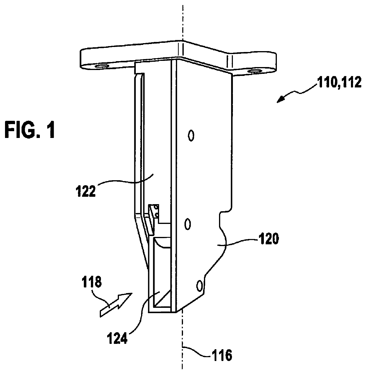
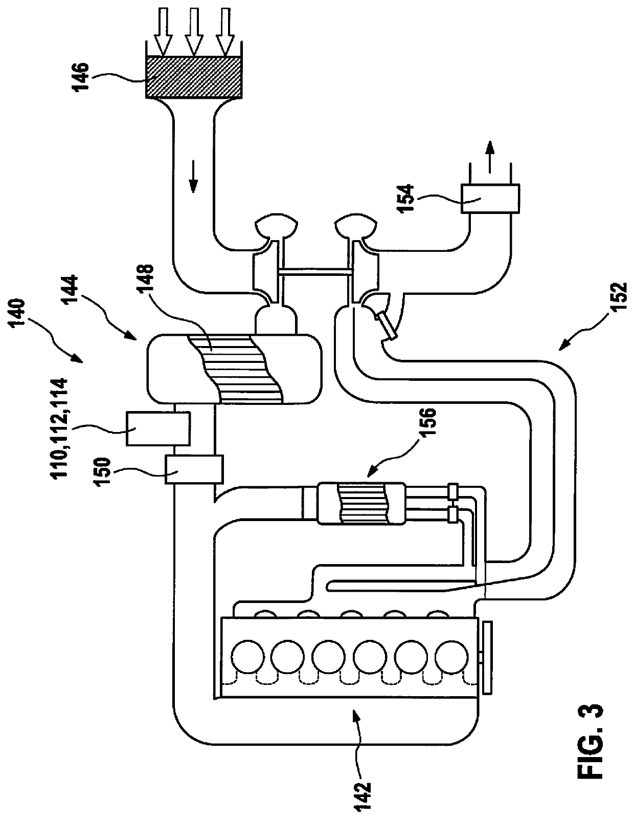
[0023]FIG. 1 shows an exemplary embodiment of a sensor element 110 according to the present invention, which may be used in the exemplary embodiment in particular as a pressure-based air mass meter 112 (PFM). Sensor element 110 is designed in particular entirely or partially as a plug sensor 114 and has a plug sensor axis 116, along which plug sensor 114 projects into a fluid medium, for example in a flow channel. The fluid medium flows against plug connector 114 in a direction of flow 118.

[0024]Sensor element 110 has a housing 120, having a front side 122, against which the fluid medium flows. An inflow opening 124 is integrated in front side 122, which may have for example, as shown in FIG. 1, a rectangular cross section and through which the fluid medium is able to enter into the interior of housing 120. This inflow opening 124 is also called an inflow contour.

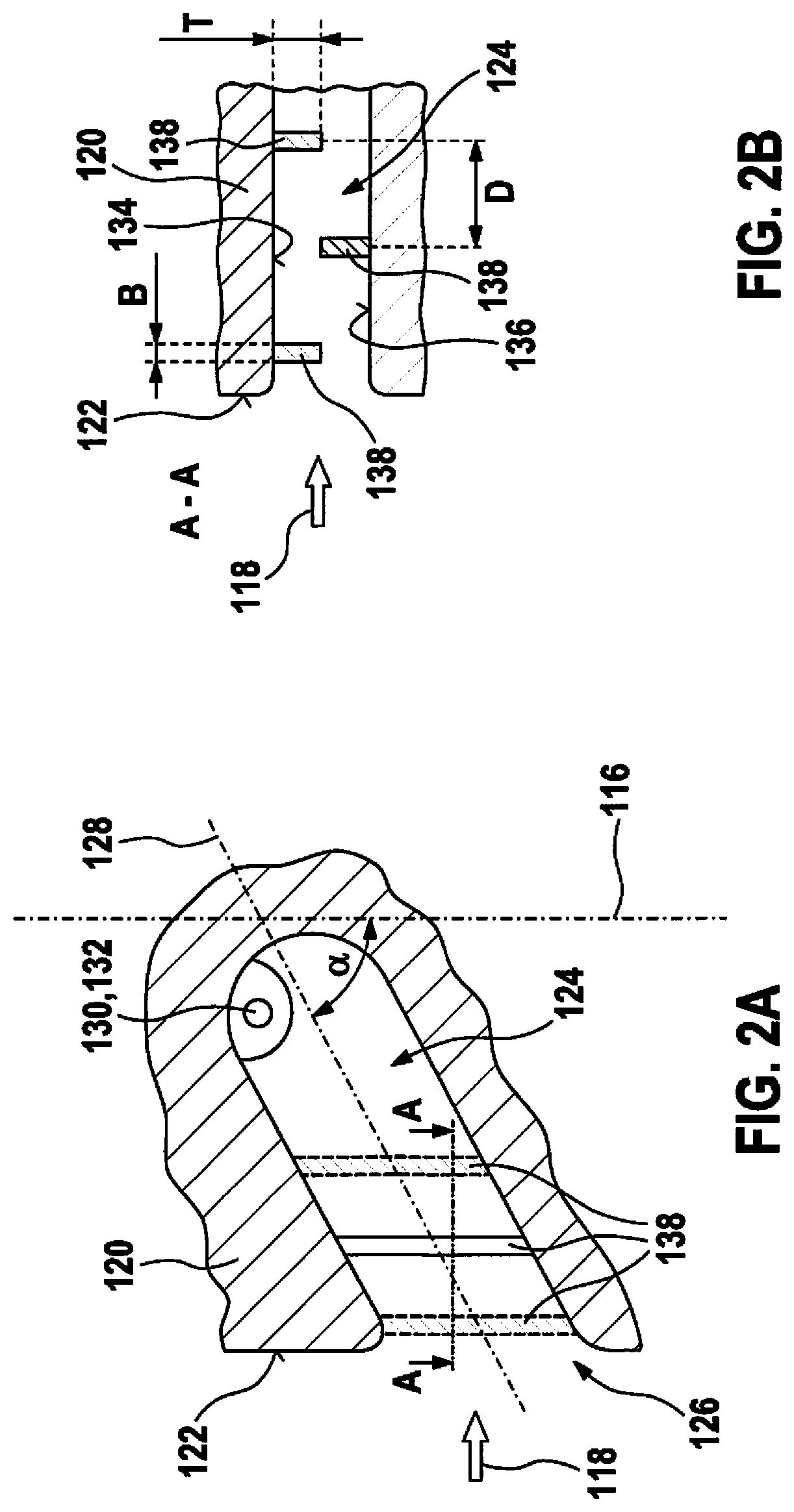
[0025]FIGS. 2A and 2B show different sectional views through housing 120. FIG. 2A shows a sectional view in a sectional p...


PUM


Abstract

A sensor element is provided for detecting at least one property of a fluid medium. The sensor element comprises at least one housing having at least one inflow opening accessible to the fluid medium. At least one pressure sensor for detecting a pressure of the fluid medium is situated in the inflow opening. In the inflow opening in front of the pressure sensor, a plurality of ribs project from at least one wall of the inflow opening into the inflow opening.

Description

BACKGROUND INFORMATION[0001]Various kinds of sensor elements for detecting at least one property of a fluid medium are available in the related art. Without limitation of further possible restrictions, the present invention is described below with reference to pressure-based air mass meters. However, other embodiments are fundamentally also possible.[0002]Thus, it is generally conventional, for example, to determine the air mass in air systems such as for example in the induction tract of an internal combustion engine using various measuring principles. Besides thermal measuring principles, for example in the form of hot-film air mass meters (HFM), pressure-based air mass measurements are also known, which are based on at least one pressure measurement. In this regard, the so-called Prandtl probes or Venturi tubes should be mentioned, for example. For example, for determining an air mass, which flows per unit of time through a tube, it is possible to measure a differential pressure ...

Claims


Application Information

Patent Timeline
Patent Type & Authority Patents(United States)
IPC IPC(8): G01F1/34G01F15/18
CPCG01F1/34G01F15/185G01F5/005G01L19/0038G01L19/0654
Inventor PLOGMANN, BENJAMIN
Owner ROBERT BOSCH GMBH
Learn More