
Coupling system

a coupling system and profile strip technology, applied in the field of coupling systems, can solve the problems of difficult to meet the requirements of the application of the coupling system, easy contamination of the sealing element from the environment side, and complicated construction of the known coupling system, so as to increase the adhesion force of the profile strip against the on

Active Publication Date: 2022-02-01
FLECOTEC
View PDF13 Cites 0 Cited by
  • Summary
  • Abstract
  • Description
  • Claims
  • Application Information

AI Technical Summary

Benefits of technology

The invention is a coupling system for transport sections, which uses only one type of closure elements to reduce production costs. The connection between closure elements is made in a way that minimizes assembly time and costs. The profile strip used in the system is designed flexible in the longitudinal direction and stable in directions transverse to it. The closure elements are stable and reliable, ensuring a secure connection. In the starting state, the profile strip has a channel that allows for a flat delimiting wall and uninterrupted media transport. The contact segment on the profile strip provides reliable closure even in the outer edge region of the connection. These technical effects help to improve the efficiency and reliability of the coupling system.

Problems solved by technology

These closure elements then can be easily contaminated from the environment side.
This contamination is undesirably carried into the inside of the hose when the coupling elements are coupled with one another that can contaminate the transported load inside the transport section, which contamination is not acceptable in particular in the case of pharmaceutical applications of the coupling system.
The known coupling system furthermore has a complicated construction due to the large number of required closure elements making it expensive to construct.
They then create the possibility of accumulation of contaminants that, in the subsequent coupling state, could undesirably arrive in the inside of the hose-shaped transport section.
Because the presented projecting closure elements for creation of the closure are pivotable for this purpose, this need to pivot once again calls for significant production expenditure, which increases the costs of the closure.

Method used


Image

  • Coupling system
  • Coupling system
  • Coupling system

Examples


Embodiment Construction

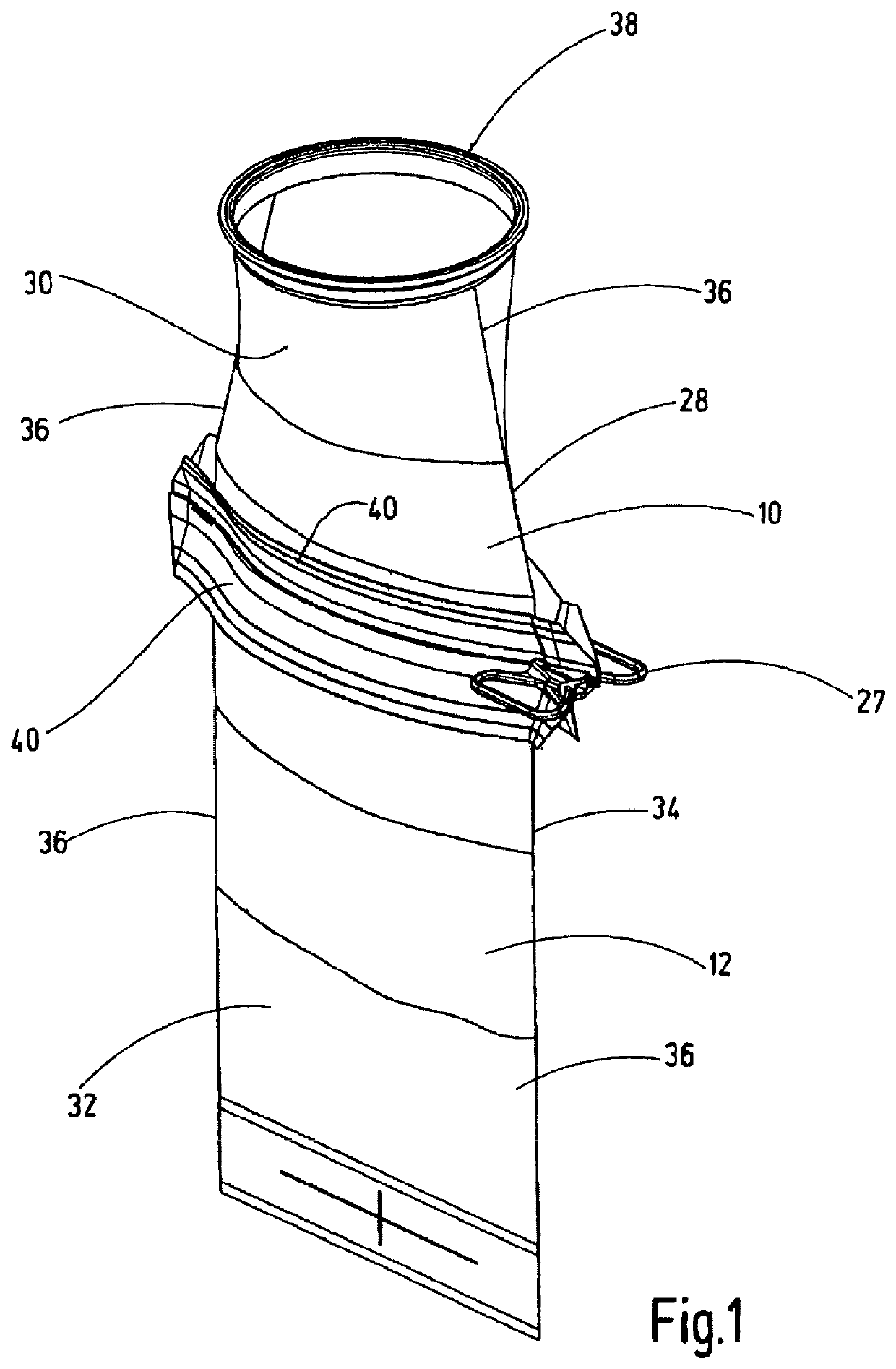
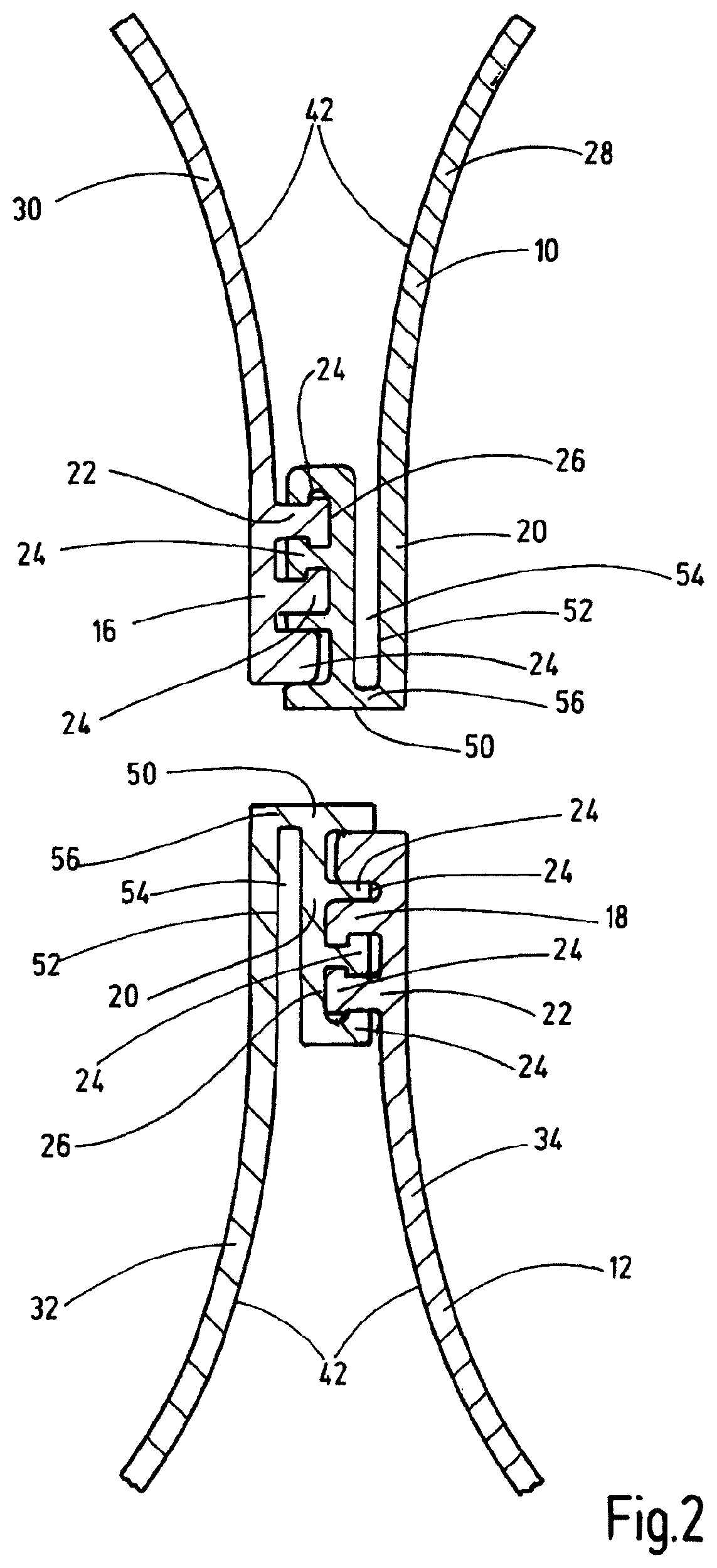
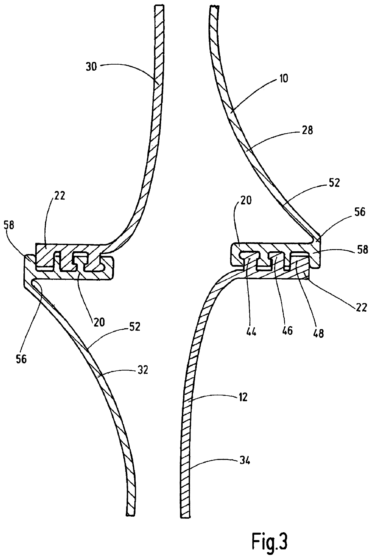
[0022]The coupling system according to the invention serves to connect in a media-conducting manner two hose-shaped sections 10, 12 in order to obtain a common transport section 14, as is depicted in particular in FIG. 4. Each section of the coupling system has a respective coupling element 16, 18, in which each coupling element has two coupling parts 20, 22 that can be separated from one another. The two coupling parts 20, 22 that can be separated from one another have individual closure elements 24, which are held together in a detachable manner along a common disconnecting point 26.

[0023]The sections 10, 12 are each formed from a foil-shaped hose made of plastic material, of which FIGS. 2 to 4 show, depicted in section, the respective front side and the back side 28, 30; 32, 34 in the bottom region thereof. These respective front and back sides 28, 30; 32, 34 are connected to one another in an integral manner at their longitudinal face sides adjacent and opposite to one another a...


PUM


Abstract

A coupling system provides a media-conducting connection of two hose-shaped sections (10, 12). Each section has one coupling element (16, 18), with two coupling parts (20, 22) that can be separated from each other and that are detachably held to each other by closure elements (24) along a disconnecting point (26). The closure parts of one coupling element can be engaged with correspondingly designed closure elements (24) of the other coupling element (20, 22) to form the transport section. All closure elements (24) of the coupling parts (20, 22) point hose-inward, at least before forming the transport section. Upon producing the transport section, the respective disconnecting point (26) is arranged between the coupling elements (16, 18), transversely to the transport section.

Description

FIELD OF THE INVENTION[0001]The invention relates to a coupling system for the media-conducting connection of two hose-like sections to form a common transport section. Each hose-shaped section has a coupling element with two coupling parts that can be separated from each other and that are detachably held together by closure elements along a disconnecting point. The coupling parts of one coupling element can be engaged with correspondingly formed closure elements of the other coupling element to form the transport section.BACKGROUND OF THE INVENTION[0002]A coupling system of this kind is known from DE 10 2009 018 565 B3, which permits an environment-proof connection of hose-shaped sections in the form of a first bundle with a second bundle. A closed docking position can be assumed and an environment-proof guidance of a media throughflow along a common transport section in a throughflow direction is permitted by the closure from the first bundle to the second bundle.[0003]The second...

Claims


Application Information

Patent Timeline
Patent Type & Authority Patents(United States)
IPC IPC(8): B65D33/25B65G51/06F16L25/00
CPCB65D33/2541B65D33/2566B65D33/2591B65G51/06F16L25/00B65D33/2508
Inventor KOCH, MARTIN
Owner FLECOTEC
Learn More