Polarized Raman spectrum coding-based nano barcode smart label
- Summary
- Abstract
- Description
- Claims
- Application Information
AI Technical Summary
Benefits of technology
Problems solved by technology
Method used
Image
Examples
embodiment 1
Coding According to Retainment and Disappearance of a Certain Peak Under the Polarization State
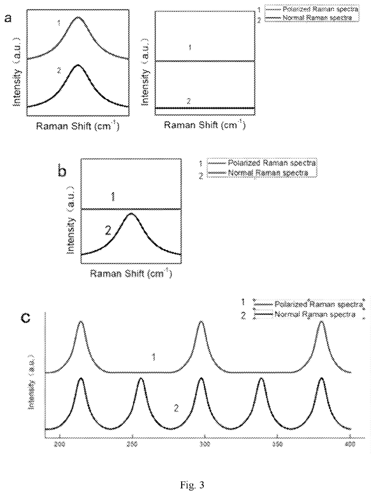
[0062]FIG. 3 is a schematic coding diagram of a peak presence state of a Raman characteristic peak under a polarization state (Curve 1) and a non-polarization state (Curve 2), wherein diagram (a) is a schematic diagram illustrating retainment of the Raman peak under the polarization state and the non-polarization state, diagram (b) is a schematic diagram illustrating a change (disappearance) of the Raman peak under the polarization state and the non-polarization state, and diagram (c) illustrates a secondary coding using a peak presence state at a specific position of the Raman characteristic peak under the polarization state and the non-polarization state.
[0063]A state code of specific position can be obtained by using the peak presence states at the specific position of the Raman spectrum detected under the non-polarization detection state and the Raman spectrum under the polarization de...
embodiment 2
Coding According to a Change in Relative Intensity of Each Peak Under a Polarization Detection State
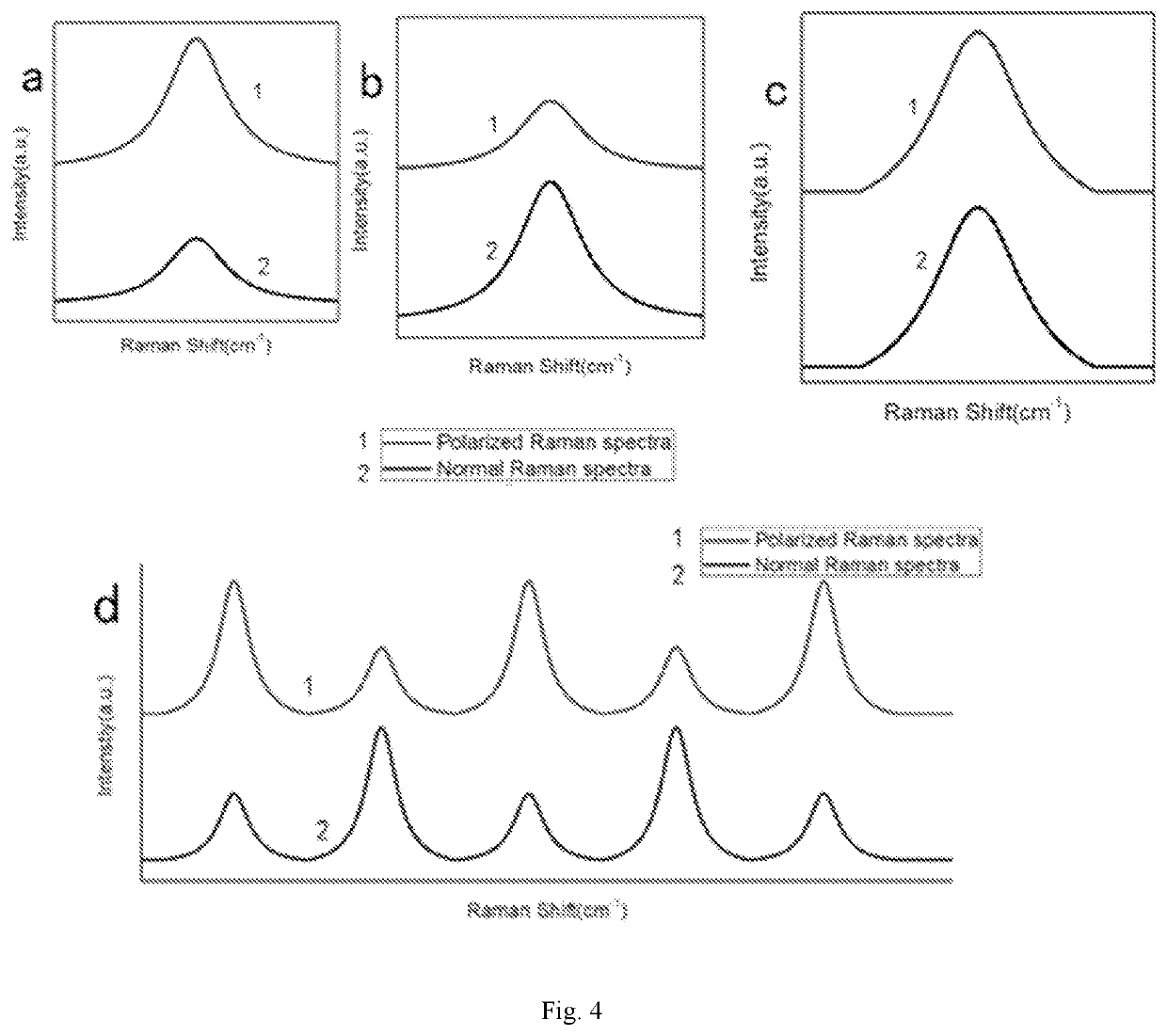
[0067]FIG. 4 is a schematic coding diagram of a peak intensity change state of a Raman characteristic peak under a polarization state (Curve 1) and a non-polarization state (Curve 2), wherein diagram (a) shows increase of the Raman peak under the polarization state over the non-polarization state, diagram (b) shows decrease of the Raman peak under the polarization state with respect to the non-polarization state, diagram (c) shows invariance of peak intensity of the Raman characteristic peak under the polarization state and the non-polarization state, and diagram (d) shows secondary coding according to the peak intensity change state at a specific position of the Raman characteristic peak under the polarization state and the non-polarization state.
[0068]Coding is performed according to a change in an intensity of a Raman peak at a specific position in a Raman spectrum detected under t...
embodiment 3
Coding According to a Shift State of a Peak Position Under a Polarization Detection State
[0070]FIG. 5 is a schematic coding diagram of a peak position shift state of a Raman characteristic peak under a polarization state (Curve 1) and a non-polarization state (Curve 2), wherein diagram (a) shows an invariance of peak position of the Raman peak under the polarization state and the non-polarization state, diagram (b) show a red shift of the Raman peak position under the polarization state and the non-polarization state, diagram (c) shows a blue shift of the Raman peak position under the polarization state and the non-polarization state, and diagram (d) shows secondary coding according to the peak position shift state at a specific position of the Raman characteristic peak under the polarization state and the non-polarization state.
[0071]Coding is performed according to a shift of peak position of a Raman peak at a specific position in a Raman spectrum detected under the non-polarizati...
PUM
 Abstract
Description
Claims
Application Information
 - R&D
- Intellectual Property
- Life Sciences
- Materials
- Tech Scout
- Unparalleled Data Quality
- Higher Quality Content
- 60% Fewer Hallucinations
Browse by: Latest US Patents, China's latest patents, Technical Efficacy Thesaurus, Application Domain, Technology Topic, Popular Technical Reports.
© 2025 PatSnap. All rights reserved.Legal|Privacy policy|Modern Slavery Act Transparency Statement|Sitemap|About US| Contact US: help@patsnap.com


