
Method and device used for wireless communication

a wireless communication and wireless communication technology, applied in the direction of electrical equipment, particular environment based services, vehicle components, etc., can solve the problems of increasing the complexity of network processing, new difficulties in the generation and reporting of charging information, and the management of the network, so as to avoid transmission of a great deal of unnecessary information, reduce the complexity, and reduce the effect of transmission

Active Publication Date: 2022-01-20
SHANGHAI LANGBO COMM TECH CO LTD
View PDF3 Cites 0 Cited by
  • Summary
  • Abstract
  • Description
  • Claims
  • Application Information

AI Technical Summary

Benefits of technology

The present patent proposes a method for generating and analyzing charging information in a communication network. The method uses two identities to indicate the source and destination of the charging information, which simplifies the charging information reported by different devices in the network. By comparing and associating the charging information with information about the sources and destinations, the network can accurately acquire and charge data statistics. The method also ensures privacy and reduces the transmission of unnecessary information. Overall, this method simplifies charging information reporting and improves network efficiency.

Problems solved by technology

In a variety of communication scenarios, such as in a UE-to-UE communication scenario where a relay exists between UEs, due to reasons of the lack of management of a central node and distributed generation of UE information, some information cannot be acquired by the network, and a UE cannot acquire another UE's information, resulting in a series of problems in management, especially in charging.
The charging involved in communications between UEs is different from the usual charging in that the charging is based on the reporting of users; which services are owned by a relay node and which services are relayed to other UEs need to be distinguished clearly to the relay node as well as to the network statistics, since this may involve different statistics and charging requirements, and if the charging information cannot be unified, the complexity of the network processing may be increased.
At the same time, due to the reasons of privacy or security, the relay UE may not be able to acquire all information of the other UEs, which brings new difficulties to the generation and reporting of charging information, especially when a link layer identity (ID) between UEs is updated.
However, when reporting charging information, since the network cannot acquire the latest users' identities, it may not exactly know the meaning of these new identities and which user these identities indicate; on the other hand, charging information reported by the relay node needs to indicate for which users or application or device or bearer or flow it serves, so that the network can charge correctly.
However, the conventional scheme cannot support the charging function of communications between UEs involving a relay.

Method used


Image

  • Method and device used for wireless communication
  • Method and device used for wireless communication
  • Method and device used for wireless communication

Examples


embodiment 1

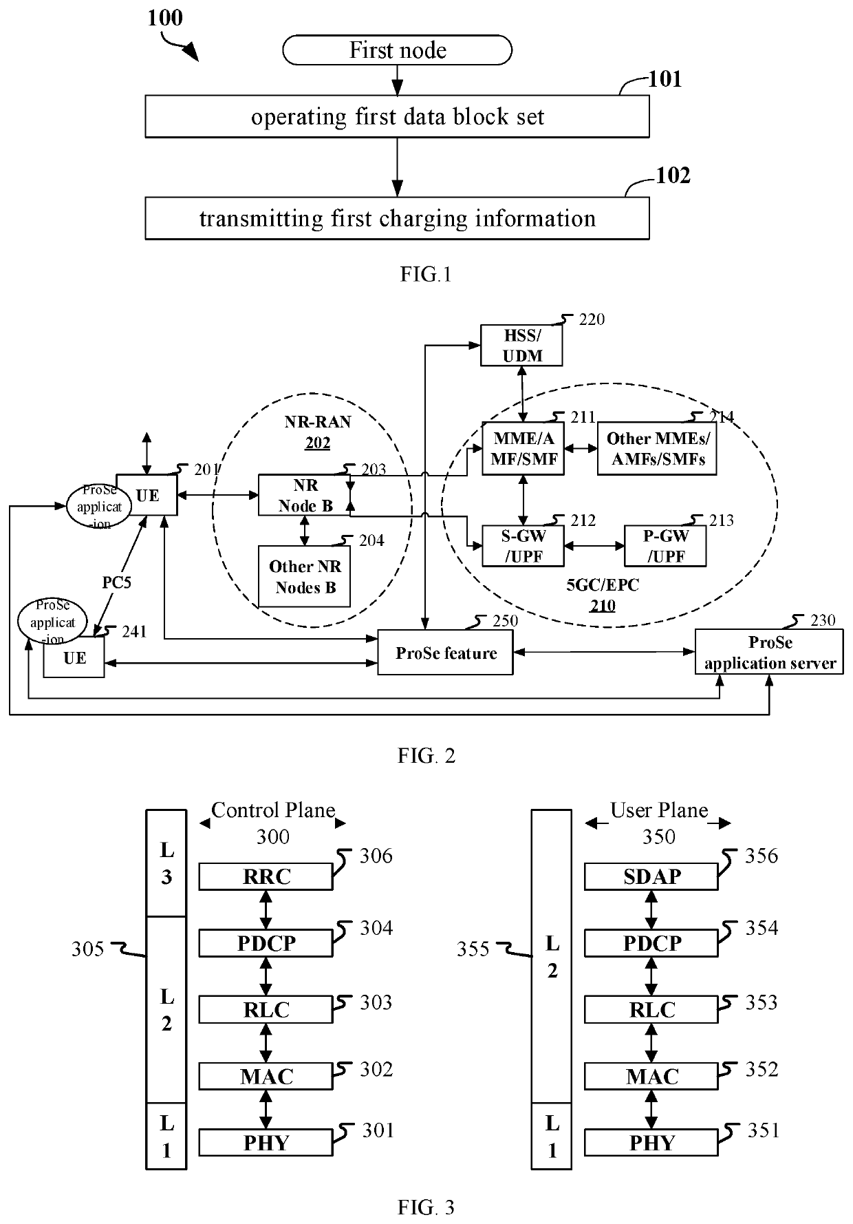
[0070]Embodiment 1 illustrates a flowchart of operating a first data block set and transmitting first charging information according to one embodiment of the present disclosure, as shown in FIG. 1. In FIG. 1, each box represents a step. Particularly, the sequential order of steps in these boxes does not necessarily mean that the steps are chronologically arranged.

[0071]In Embodiment 1, a size of data in the first data block set is used to generate the first charging information, the first charging information comprises a first ID set, and the first ID set comprises a first ID and a second ID; the first ID is a link layer ID; the operating action is receiving, a destination ID field of a MAC header of a MAC PDU used to carry the first data block set comprises at least partial bits in a first ID, when a destination link layer ID list maintained by a node indicated by the second ID comprises the first ID, the first ID identifies a receiver of the first data block set, and when a destin...

embodiment 2

[0250]Embodiment 2 illustrates a schematic diagram of a network architecture according to one embodiment of the present disclosure, as shown in FIG. 2. FIG. 2 is a diagram illustrating a V2X communication architecture of 5G NR, Long-Term Evolution (LTE), and Long-Term Evolution Advanced (LTE-A) systems. The 5G NR or LTE network architecture may be called a 5G System / Evolved Packet System (5GS / EPS) 200 or other appropriate terms.

[0251]The V2X communication architecture in Embodiment 2 may comprise a UE 201, a UE 241 in communication with UE 201, an NG-RAN 202, a 5G Core Network / Evolved Packet Core (5GC / EPC) 210, a Home Subscriber Server (HSS) / Unified Data Management (UDM) 220, a ProSe feature 250 and a ProSe application server 230. The V2X communication architecture may be interconnected with other access networks. For simple description, the entities / interfaces are not shown. As shown in FIG. 2, the V2X communication architecture provides packet switching services. Those skilled in ...

embodiment 3

[0259]Embodiment 3 illustrates a schematic diagram of an example of a radio protocol architecture of a user plane and a control plane according to one embodiment of the present disclosure, as shown in FIG. 3. FIG. 3 is a schematic diagram illustrating an embodiment of a radio protocol architecture of a user plane 350 and a control plane 300. In FIG. 3, the radio protocol architecture for a first node (UE, gNB or a satellite or an aircraft in NTN) and a second node (gNB, UE or a satellite or an aircraft in NTN), or between two UEs is represented by three layers, which are a layer 1, a layer 2 and a layer 3, respectively. which are a layer 1, a layer 2 and a layer 3, respectively. The layer 1 (L1) is the lowest layer and performs signal processing functions of various PHY layers. The L1 is called PHY 301 in the present disclosure. The layer 2 (L2) 305 is above the PHY 301, and is in charge of a link between a first node and a second node, as well as two UEs via the PHY 301. L2 305 com...


PUM


Abstract

The present disclosure method and device for wireless communications, comprising: operating a first data block set; and transmitting first charging information; a size of data in the first data block set is used to generate the first charging information, the first charging information comprises a first identity (ID) set, and the first ID set comprises a first ID and a second ID; the first ID is a link layer ID; the operating action is receiving, a destination ID field of a MAC header of a MAC PDU used to carry the first data block set comprises at least partial bits in a first ID, when a destination link layer ID list maintained by a node indicated by the second ID comprises the first ID. The present disclosure determines a receiver or a generator of a first data block set, which improves accuracy of charging and enriches charging types of services.

Description

CROSS REFERENCE TO RELATED APPLICATIONS[0001]This application claims the priority benefit of Chinese Patent Application CN202010686444.0, filed on Jul. 16, 2020, the full disclosure of which is incorporated herein by reference.BACKGROUNDTechnical Field[0002]The present disclosure relates to transmission methods and devices in wireless communication systems, and in particular to a method and device for reporting user information, ensuring data consistency and charging in wireless communications.Related Art[0003]Application scenarios of future wireless communication systems are becoming increasingly diversified, and different application scenarios have different performance demands on systems. In order to meet different performance requirements of various application scenarios, the 3rd Generation Partner Project (3GPP) Radio Access Network (RAN) #72 plenary decided to conduct the study of New Radio (NR), or what is called fifth Generation (5G). The work Item (WI) of NR was approved at...

Claims


Application Information

Patent Timeline
IPC IPC(8): H04W4/24H04M15/00H04W88/04H04W72/04
CPCH04W4/24H04M15/67H04M15/765H04W4/46H04W72/0406H04M15/8214H04W88/04H04W12/02H04W12/06H04W72/20
Inventor ZHANG, XIAOBO
Owner SHANGHAI LANGBO COMM TECH CO LTD
Learn More