
Production feasible pendulum crankshaft

a technology of pendulum crankshaft and crankshaft, which is applied in the field of absorbers, can solve the problems of increasing construction cost, high crankshaft torsional vibration, and high vibration of engine blocks,

Active Publication Date: 2015-10-08
FORD GLOBAL TECH LLC
View PDF10 Cites 3 Cited by
  • Summary
  • Abstract
  • Description
  • Claims
  • Application Information

AI Technical Summary

Benefits of technology

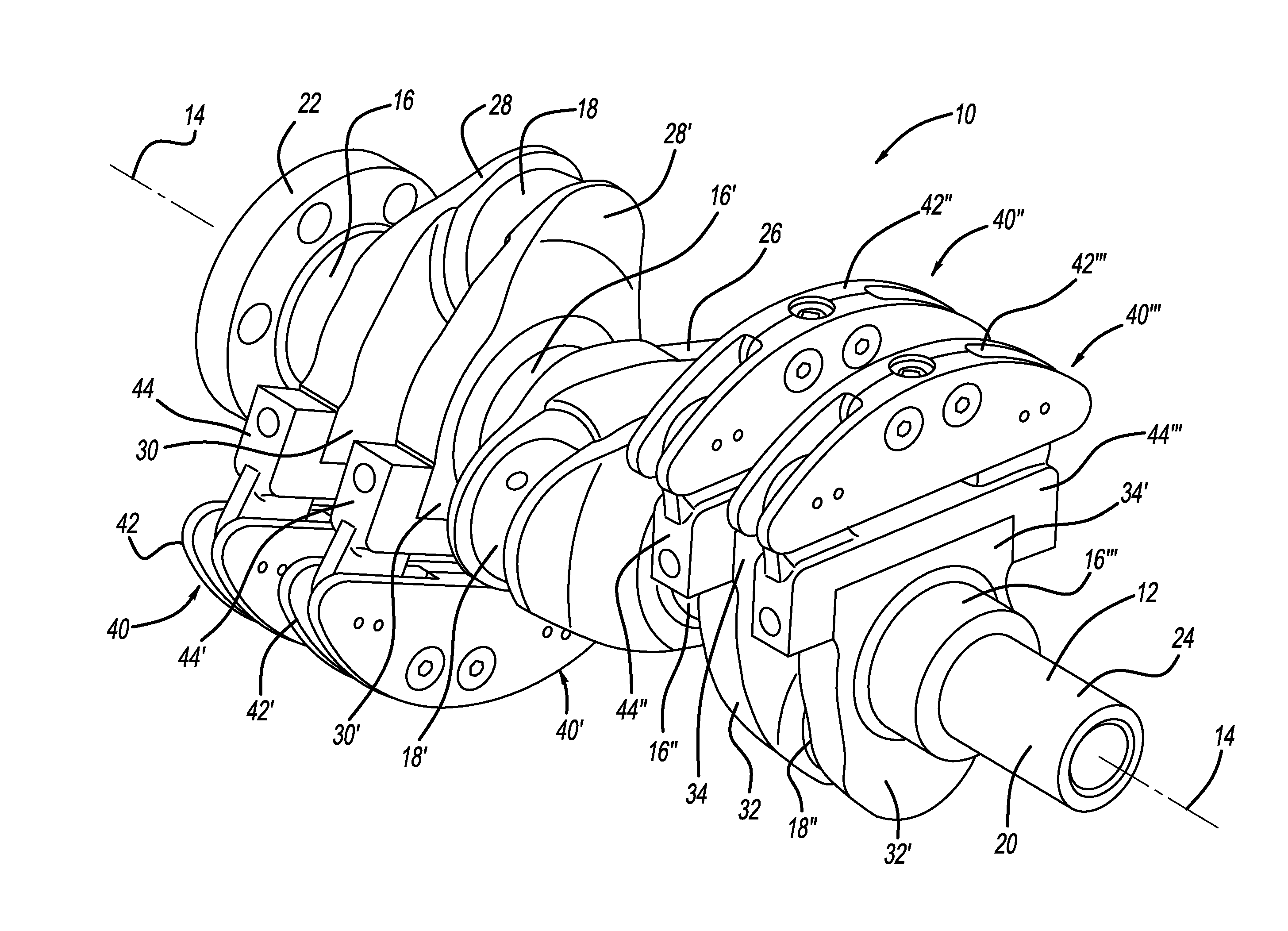
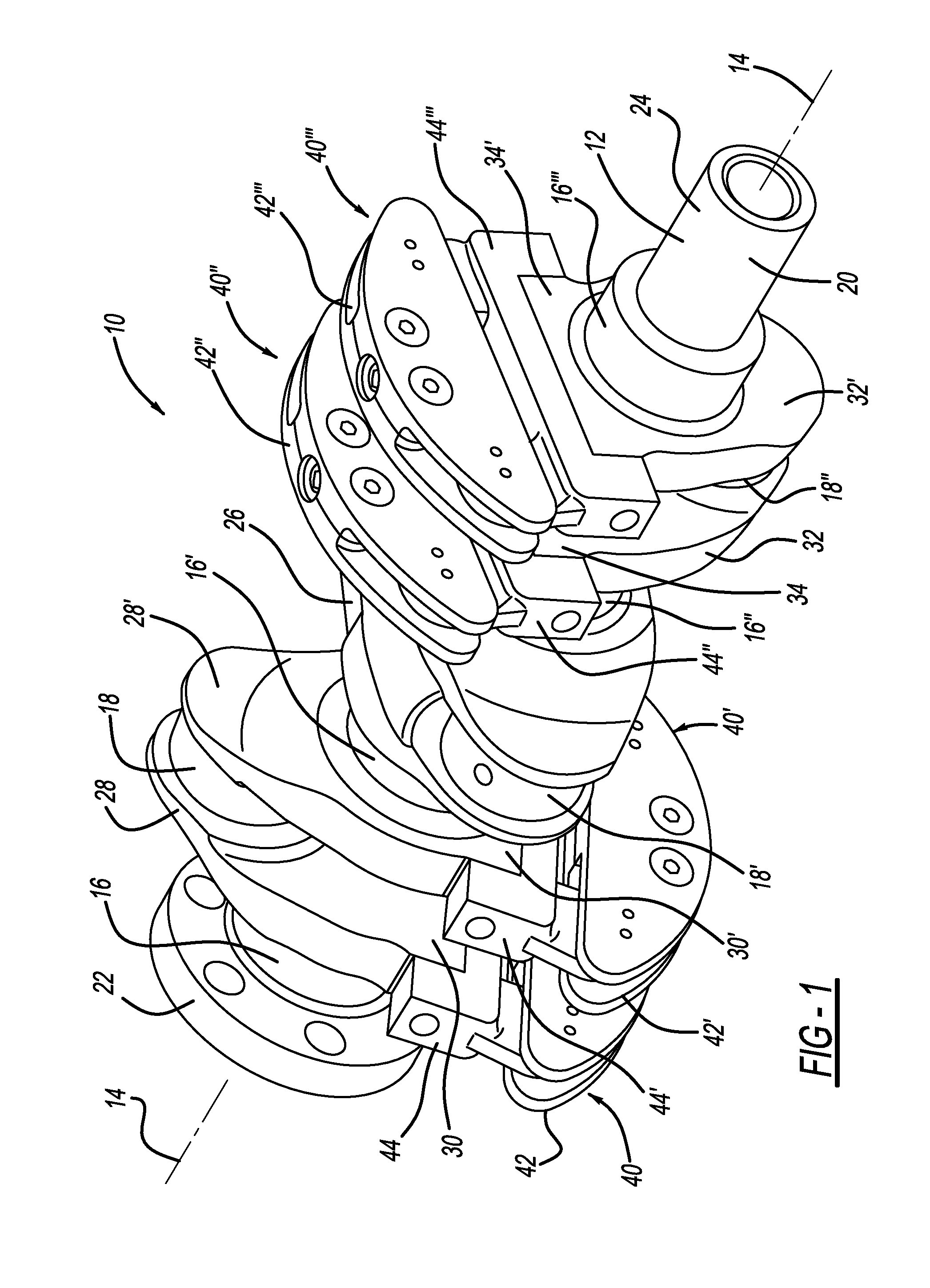
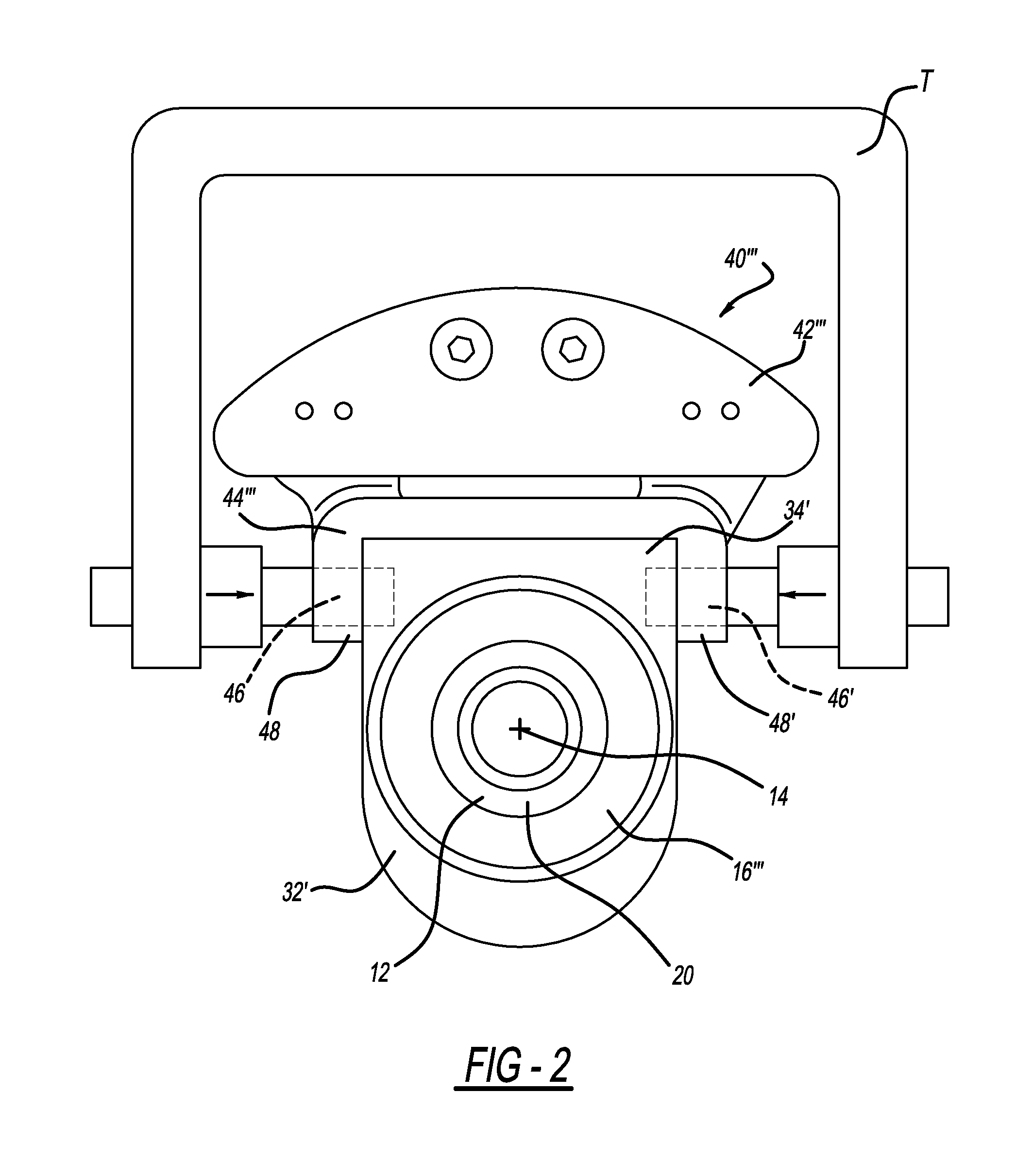
The disclosed inventive concept is a solution for reducing torsional vibrations in small internal combustion engines, such as three cylinder engines. It overcomes issues with existing methods by using a pair of fasteners that attach the pendulum carrier to the pendulum carrier attachment boss on the crankshaft. The fasteners can be pressed pins, shrink-fit pins, shoulder bolts, Z-Form fastener assemblies, or rivets. This arrangement ensures that the pendulum carrier remains secure and prevents it from moving relative to the crankshaft. This method is practical for production and avoids the issues of slipping and failure of attachment bolts in shear.

Problems solved by technology

An undesirable consequence of engines with a small number of cylinders is high crankshaft torsional vibration and high engine block vibration caused by forces, such as first and second order forces, that are not cancelled.
Engineers managed these vibrations to one extent or another through a variety of approaches, many of which increase the cost of construction and reduce fuel economy.
However, attachment to the crankshaft has been calculated to result in bolt failure at high speed due to sheer.
The prototype method of attaching a pendulum crankshaft is not feasible in production.
This method is not feasible since the clamp load is not sufficient to prevent the pendulum from moving radially.
The clamp load interface would slip and bolts would fail in sheer.

Method used


Image

  • Production feasible pendulum crankshaft
  • Production feasible pendulum crankshaft
  • Production feasible pendulum crankshaft

Examples


third embodiment

[0038]mechanical attachment according to the disclosed inventive concept is illustrated in FIG. 4 in which an end view of the pendulum assembly 40″′ attached to the crankshaft 12 is attached by shoulder bolts 60 and 60′ is shown. The shoulder bolt 60 includes a shoulder 62 and a threaded end 64. The shoulder bolt 60′ includes a shoulder 60′ and a threaded end 64′. The bolts 60 and 60′ may be of a variety of diameters, though a non-limiting diameter may be 8.0 mm.

[0039]The shoulder bolts 60 and 60′ pass through holes formed in the ears 48 and 48′ of the pendulum carrier 44″′ and into threaded holes formed in alignment in the pendulum carrier attachment boss 34′. The shoulders 62 and 62′ have a tight fit relative to the holes formed in the ears 48 and 48′ of the pendulum carrier 44″′ and in the pendulum carrier attachment boss 34′.

fourth embodiment

[0040]mechanical attachment according to the disclosed inventive concept is illustrated in FIG. 5 in which an end view of the pendulum assembly 40″′ attached to the crankshaft 12 is attached by Z-Form™ fastener assemblies 70 and 70′ is shown. (Z-Form™ is a product of Acument Global Technologies.) The fastener assembly 70 includes a shoulder bolt 72 and a pre-assembled deformable sleeve 74. The shoulder bolt 72 includes a shoulder 76 and a threaded end 78. The fastener assembly 70′ includes a shoulder bolt 72′ and a pre-assembled deformable sleeve 74′. The shoulder bolt 72′ includes a shoulder 76′ and a threaded end 78′. The shoulder bolts 72 and 72′ may be of a variety of diameters, though a non-limiting diameter may be 8.0 mm.

[0041]The pre-assembled deformable sleeves 74 and 74′ pass through holes formed in the ears 48 and 48′ of the pendulum carrier 44″′ and into holes formed in the pendulum carrier attachment boss 34′. The pre-assembled deformable sleeves 74 and 74′. The shoulder...

fifth embodiment

[0042]mechanical attachment according to the disclosed inventive concept is illustrated in FIG. 6 in which an end view of the pendulum assembly 40″′ attached to the crankshaft 12 is attached by blind rivets 80 and 80′ is shown. The blind rivet 80 includes a rivet head 82 and a shank 84 extending therefrom. An upset head 86 is formed at the end of the shank 84 after the blind rivet 80 is attached. A cavity 88 is formed in the pendulum carrier attachment boss 34′ to accommodate the upset head 86. A retained mandrel head 90 forms the upset head 86 as is known in the art.

[0043]The blind rivet 80′ includes a rivet head 82′ and a shank 84′ extending therefrom. An upset head 86′ is formed at the end of the shank 84′ after the blind rivet 80′ is attached. A cavity 88′ is formed in the pendulum carrier attachment boss 34′ to accommodate the upset head 86′. A retained mandrel head 90′ forms the upset head 86′, again as is known in the art.

[0044]Whether pressed pins 46 and 46′, the shrink-fit ...


PUM


Abstract

A pendulum absorber fixed to the crankshaft of an engine comprises a pendulum and a pendulum carrier attached to the pendulum carrier attachment boss of the crankshaft. Each pendulum carrier has a pair of parallel ears extending therefrom. The carrier is tightly attached to the attachment boss such that the attachment boss is captured between the ears of the carrier. Attachment of the pendulum carrier to the sides of the attachment boss allows for feasibility in production, unlike known arrangements which require attachment of the pendulum carrier to the top of the crankshaft web. The fastener may be a pair of pressed-in pins, a single shrink-fit pin, shoulder bolts, Z-Form™ fastener assemblies, or rivets. Regardless of the type of fastener used, the side attachment arrangement of the disclosed inventive concept are sufficient to carry the load in sheer and prevent the pendulum assemblies from moving relative to the crankshaft.

Description

TECHNICAL FIELD[0001]The disclosed inventive concept relates generally to absorbers to reduce torsional vibration in an internal combustion engine. More particularly, the disclosed inventive concept relates to pendulum absorbers mounted by fasteners including one or more pressed-in pins, bolts or rivets attached to the side of the crankshaft to facilitate production assembly.BACKGROUND OF THE INVENTION[0002]Internal combustion engines having a relatively small number of cylinders provide automobile makers with an attractive solution to the need for improved fuel economy. In order to compensate for reduction of cubic capacity vehicle manufacturers developed technologies to improve engine power, such as direct fuel injection, turbocharging, and variable timing for inlet and exhaust camshafts. In this way six- and eight-cylinder engines can be scaled down without losing available horsepower.[0003]An undesirable consequence of engines with a small number of cylinders is high crankshaft ...

Claims


Application Information

Patent Timeline
Patent Type & Authority Applications(United States)
IPC IPC(8): F16F15/26F16F15/14
CPCF16F15/145F16F15/26F16F15/283F16F15/34F16F15/286F16C3/20
Inventor BREVICK, JOHN EDWARDCHOTTINER, JEFFREY ELIOTWILLIAMS, RICK L.KOPMANIS, MIKE A.
Owner FORD GLOBAL TECH LLC
Learn More