Endoscope system

a technology of endoscope and insertion portion, which is applied in the field of bend stiffness of the insertion portion, can solve the problems of not being able to make the overtube too long, and achieve the effects of preventing warpage (deflection), facilitating the insertion of the endoscope, and preventing warpage (deflection)

Active Publication Date: 2022-02-15
FUJIFILM CORP
View PDF95 Cites 0 Cited by
  • Summary
  • Abstract
  • Description
  • Claims
  • Application Information

AI Technical Summary

Benefits of technology

[0007]The present invention is made considering such circumferences, and aims to provide an endoscope system which can secure appropriate bending stiffness of an insertion portion while maintaining the slide length of the insertion portion.
[0019]As described above, according to an endoscope system of the present invention, it is possible to secure appropriate bending stiffness of an insertion portion while maintaining the slide length of the insertion portion.

Problems solved by technology

Meanwhile, if the whole length of the overtube is made relatively long relative to the insertion portion in order to secure bending stiffness, since slidable length becomes short and insertion itself becomes difficult, it is not possible to make the overtube too long.

Method used


Image

  • Endoscope system
  • Endoscope system
  • Endoscope system

Examples


example 1

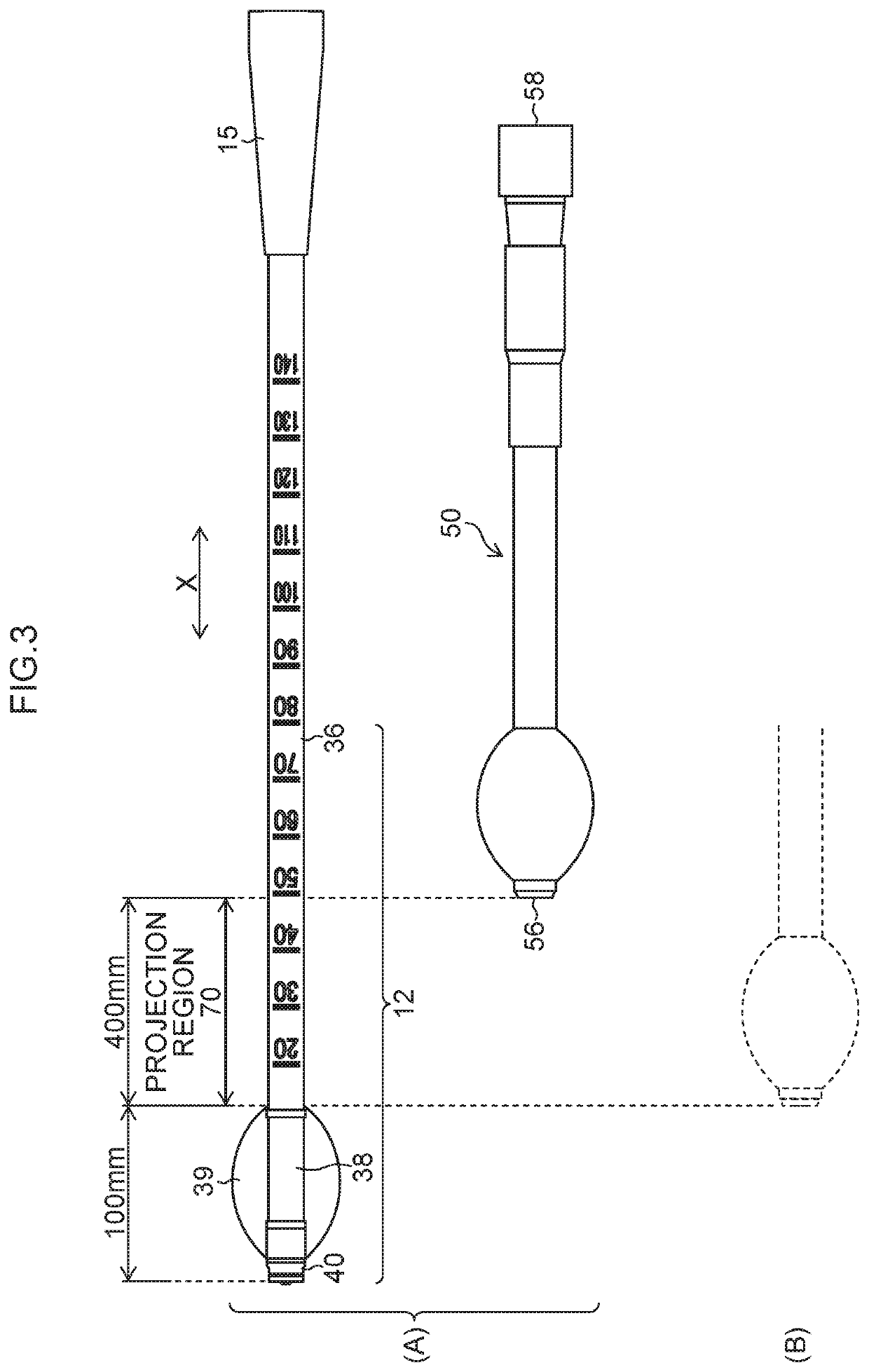
[0053]FIG. 5 is a graph illustrating the state of a bending stiffness change in Example 1. In Example 1, the bending stiffness change portion 80 is provided over the full range of the above-mentioned projection region 70 (the region of the flexible portion 36 that projects from the distal end opening 56 of the overtube 50 in a state where the insertion portion 12 is located in the distal end position in a movable range with respect to the overtube 50, that is, in a state where the insertion portion 12 is moved until the boot 15 abuts on the inner edge of the proximal end opening 58). Specifically, as illustrated in FIG. 5, a first position P1 in which the bending stiffness begins to increase is located at a position apart by 100 mm from the distal end of the insertion portion 12 (the distal end surface of the distal-end hard portion 40), a second position P2 in which the increase in the bending stiffness ends is located at a position apart by 500 mm from the distal end, and the leng...

example 2

[0057]FIG. 6 is a graph illustrating the state of a bending stiffness change in Example 2. In Example 2, the bending stiffness uniform portion 82 is provided in a range of 100 mm from the connection portion between the bending portion 38 and the flexible portion 36. In this bending stiffness uniform portion 82, the bending stiffness is constant (the bending stiffness is the least in the flexible portion 36) along the longitudinal axis direction of the flexible portion 36 (the X direction in FIG. 3). The most-proximal end-side position of the bending stiffness uniform portion 82 is a first position P1 in Example 2, the bending stiffness change portion 80 is provided in a range of 300 mm from this first position P1 to second position P2 on the proximal end side, and the bending stiffness gradually increases. The proximal end side than the second position P2 is covered with the overtube 50. Here, in a similar way to Example 1, when the bending stiffness in the first position P1 is assu...

example 3

[0059]FIG. 8 is a graph illustrating the state of a bending stiffness change in Example 3. In Example 3, the bending stiffness change portion 80 is provided on the further proximal end side than the projection region 70 in addition to the full range of the above-mentioned the projection region 70. Specifically, as illustrated in FIG. 8, a first position P1 in which bending stiffness begins to increase is located at a position apart by 100 mm from the distal end of the insertion portion 12, and an increase in the bending stiffness ends at a third position P3 (third position) (apart by 600 mm from the distal end) on the proximal end side further apart by 100 mm from a second position P2, over the second position P2 (the projection region 70 ends here) that is a position apart by 500 mm from the distal end. In a similar way to Examples 1 and 2, when the bending stiffness in the first position P1 is assumed to be 1, the bending stiffness (relative ratio) in the third position P3 is assu...


PUM


Abstract

There is provided an endoscope system which can secure appropriate bending stiffness of an insertion portion while maintaining the slide length of an endoscope insertion portion. According to one aspect of one of the present invention, in an endoscope system including an endoscope and an insertion assisting tool in which the endoscope is inserted and which assists the insertion of an endoscope insertion portion into a body, a flexible portion of the endoscope insertion portion includes a projection region which projects from the distal end opening of a tube body when the endoscope insertion portion is located in the distal end position in a movable range with respect to the tube body of the insertion assisting tool, and the projection region includes a bending stiffness change portion in which bending stiffness increases from a first position on the distal end side to a second position on the proximal end side.

Description

CROSS-REFERENCE TO RELATED APPLICATIONS[0001]The patent application claims priority under 35 U.S.C. § 119 to Japanese Patent Application No. 2015-021096, filed on Feb. 5, 2015. Each of the above application(s) is hereby expressly incorporated by reference, in its entirety, into the present application.BACKGROUND OF THE INVENTIONField of the Invention[0002]The present invention relates to an endoscope system which combines and uses an endoscope and an insertion assisting tool, and particularly relates to the bending stiffness of an insertion portion of an endoscope.Description of the Related Art[0003]An endoscope may be used in the diagnosis and operation of a stomach, a duodenum and a small intestine, and so on. Further, it is known that the hardness of an insertion portion of the endoscope is changed according to the operator's operation in order to improve the insertion performance of the endoscope at diagnosis and operation (for example, see Japanese Patent Application Laid-Open ...

Claims


Application Information

Patent Timeline
Patent Type & Authority Patents(United States)
IPC IPC(8): A61B1/00A61B1/005A61B1/31
CPCA61B1/00078A61B1/005A61B1/0051A61B1/00071A61B1/00082A61B1/00154A61B1/31A61B1/00066A61B1/00131A61B1/273A61B1/009
Inventor TAKAHASHI, NOBUHARUMATSUSHITA, MOTOHIKOIDE, TAKURO
Owner FUJIFILM CORP
Why Eureka
Try Eureka