In-line thermal break

a technology of in-line thermal break and gas sample, which is applied in the direction of removing sample devices, pipe protection, thermal insulation of pipe protection, etc., can solve the problems of anomalous sample analysis, heat leakage, condensation, freezing, etc., and achieve the effect of reducing heat migration

Active Publication Date: 2022-02-15
MUSTANG SAMPLING
View PDF37 Cites 2 Cited by
  • Summary
  • Abstract
  • Description
  • Claims
  • Application Information

AI Technical Summary

Benefits of technology

[0005]It is an object of the present invention to provide an improved adjunct to

Problems solved by technology

Sample line temperature control is a known problem in the field of gas sample conditioning, particularly with respect to cryogenic liquids such as LNG.
Heat generated from gas separation or vaporization proces

Method used


Image

  • In-line thermal break
  • In-line thermal break
  • In-line thermal break

Examples


Embodiment Construction

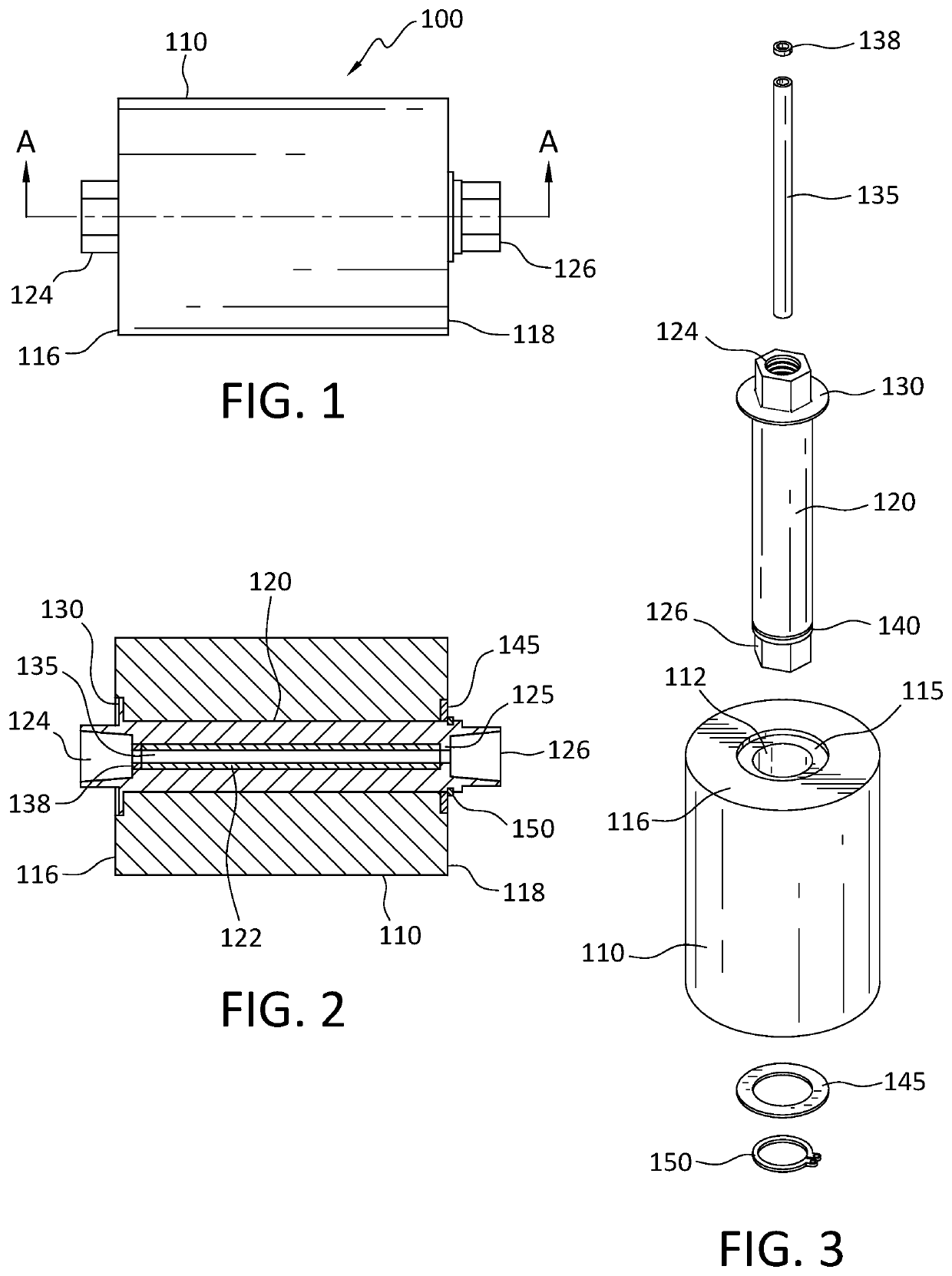
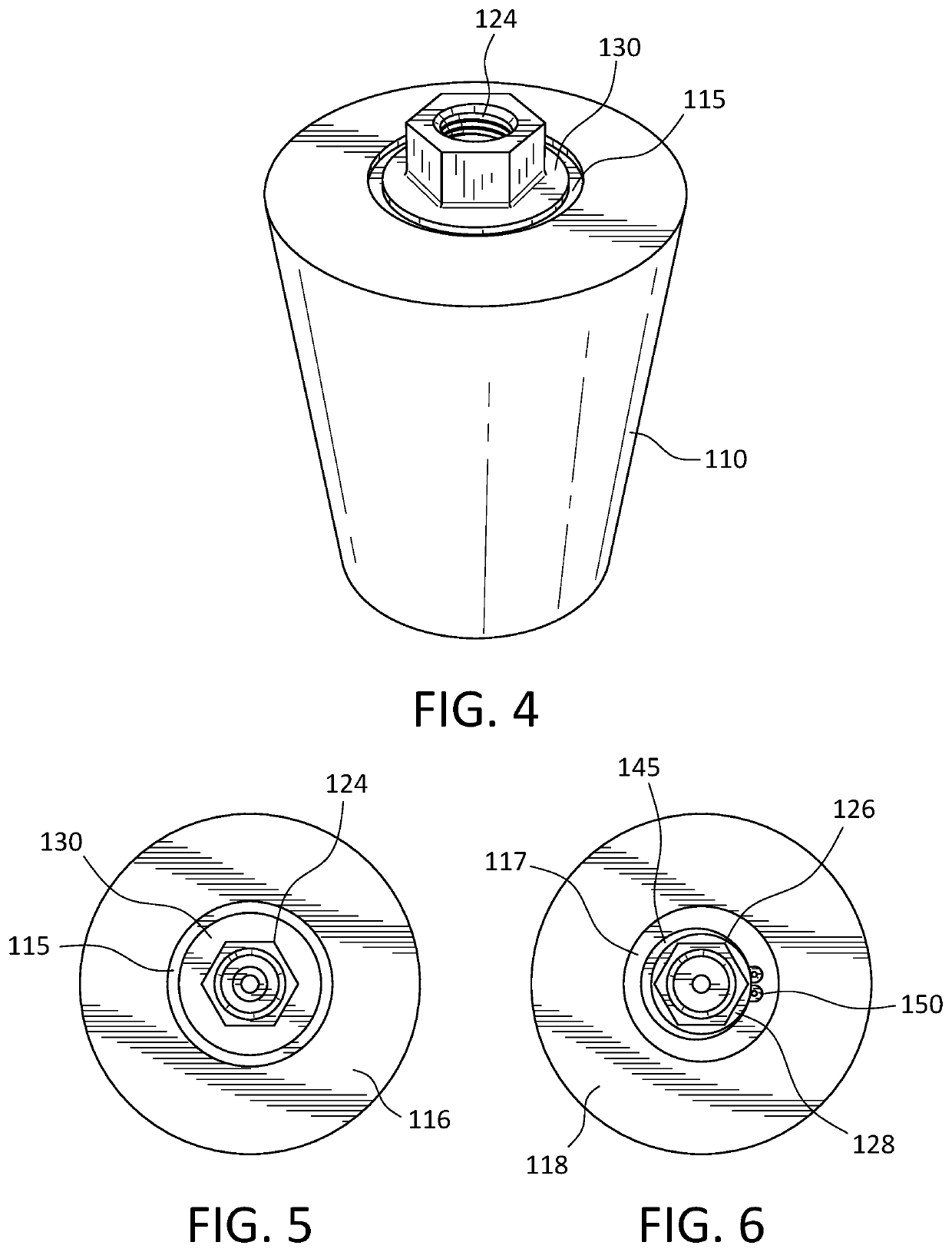
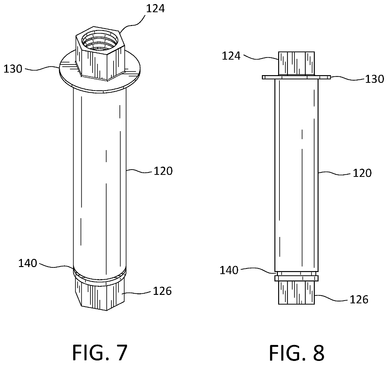
[0040]FIGS. 1-6 depict a thermal break construct 100 contemplated by an embodiment of the invention. Thermal break 100 includes concentrically disposed arranges: 1) a thermal insulating outer shell body 110, 2) an elongated insert member 120 incorporating integrated pipe fitting elements at the input and output ends with a collared axial bore extending therebetween, where the insert member 120 is substantially telescopically seated within and projecting from both ends of the insulating shell body 110, and 3) an interior, hydraulic pressure burst resistant fluid liner tube 135 having an outer peripheral surface corresponding to the diameter of the axial bore of the insert member 120 to be concentrically disposed therein with a length less than that the axial bore, and an outer wall with a fluid communication channel dimensionally corresponding to the internal collar of the insert member 120 so as to snuggly seat within and abut and dimensionally correspond to the thickness of the col...


PUM


Abstract

A multi-component in-line thermal break including concentrical arranges, an outer thermally insulating body, an elongated axial insert incorporating integrated pipe fittings, and a thermally non-conductive fluid channel tube set within the elongated axial insert.

Description

BACKGROUND[0001]Sample line temperature control is a known problem in the field of gas sample conditioning, particularly with respect to cryogenic liquids such as LNG. Heat generated from gas separation or vaporization process(es) can migrate into the feed line or source channel of a gas sample conditioning system, leading to anomalous sample analysis, heat leakage, condensation, icing, freezing, and / or other undesirable effects.[0002]In-line gas sample vaporization technology provides vaporized gas samples for composition and energy content analysis. Minimization of heat migration prior to introduction of a liquid sample to a vaporizer is desired in in-line systems to maintain specific temperature, pressure and velocity conditions in order to avoid pre-vaporization and its adverse effect on accurate sample analysis.[0003]To achieve effective in-line thermal isolation, in addition to providing an effective thermal insulation capacity to prevent heat migration, an isolator construct ...

Claims


Application Information

Patent Timeline
IPC IPC(8): F16L59/14F16L59/06
CPCF16L59/14F16L59/06G01N1/22
Inventor THOMPSON, KENNETH OWARNER, KEVINPALUCH, WILLIAM C.
Owner MUSTANG SAMPLING
Why Eureka
Try Eureka