Check patentability & draft patents in minutes with Patsnap Eureka AI!

Package structure and manufacturing method thereof

a packaging structure and manufacturing method technology, applied in the field of packaging structure, can solve the problems of manufacturing cost, and achieve the effect of reducing manufacturing cost and effective enhancing the reliability of the package structur

Active Publication Date: 2022-02-15
POWERTECH TECHNOLOGY
View PDF8 Cites 0 Cited by
  • Summary
  • Abstract
  • Description
  • Claims
  • Application Information

AI Technical Summary

Benefits of technology

[0003]The disclosure provides a package structure and a manufacturing method thereof, which provides passive component integration while effectively enhancing the reliability of the package structure at a lower manufacturing cost.
[0006]Based on the above, the frame structure within the package structure serves as electrical connection between the passive component and the redistribution structure. Thus, the conventional use of conductive pillars for connection through the encapsulation layer to the redistribution layer may be eliminated. In other words, the costly tall pillar plating process in a conventional manufacturing process of the package structure may be removed to reduce the cost of fabrication. The frame structure may also serve as a carrier during the manufacturing process of the package structure. Thus, the use of a temporary carrier may be eliminated. In other words, the costly transfer bonding process performed in the conventional manufacturing process of the package structure may be removed to reduce the cost of fabrication. Moreover, since the frame structure may be formed by rigid materials, the frame structure is able to provide rigidity and strength to the package structure, while keeping the package structure thin. As such, the problems of panel warpage and package chipping / breaking / cracking may be sufficiently prevented, thereby increasing the yield and the reliability of the package structure. Furthermore, the frame structure may also serve the function of heat dissipation and electromagnetic interference (EMI) shielding. As a result, the performance of the package structure having integrated passive components may be further enhanced.

Problems solved by technology

Continuing to miniaturize the package structure while keeping the cost of manufacturing low and the performance of the packaged semiconductor die high continues to be a challenge to researchers in the field.

Method used


Image

  • Package structure and manufacturing method thereof
  • Package structure and manufacturing method thereof
  • Package structure and manufacturing method thereof

Examples


Embodiment Construction

[0015]Reference will now be made in detail to the present preferred embodiments of the invention, examples of which are illustrated in the accompanying drawings. Wherever possible, the same reference numbers are used in the drawings and the description to refer to the same or like parts.

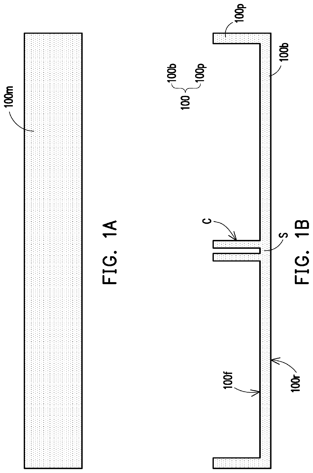
[0016]FIG. 1A to FIG. 1J are schematic cross-sectional views illustrating a manufacturing method of a package structure 10 according to an embodiment of the disclosure. FIG. 2 is a top view of an intermediate step in a manufacturing method of a package structure 10 shown in FIG. 1B according to an embodiment of the disclosure. Referring to FIG. 1A, a plate 100m is provided. The plate 100m may be made of a conductive material. For example, the material of the plate 100m includes copper, metallic alloy, steel, or a combination thereof. Referring to FIG. 1B, a portion of the plate 100m may be removed or the plate 100m may be shaped to form a frame structure 100. For example, the plate 100m may by etched...


PUM


Abstract

A package structure including a frame structure, a die, an encapsulant, a redistribution structure, and a passive component is provided. The frame structure has a cavity. The die is disposed in the cavity. The encapsulant fills the cavity to encapsulate the die. The redistribution structure is disposed on the encapsulant, the die, and the frame structure. The redistribution structure is electrically coupled to the die. The passive component is disposed on the frame structure and electrically coupled to the redistribution structure through the frame structure. A manufacturing method of a package structure is also provided. The frame structure may provide support, reduce warpage, dissipate heat from the die, act as a shield against electromagnetic interference, and / or provide electrical connection for grounding.

Description

BACKGROUND OF THE INVENTIONField of the Invention[0001]The disclosure generally relates to a package structure and a manufacturing method thereof, and in particular, to a package structure having a frame structure and an integrated passive component and a manufacturing method of the package structure.Description of Related Art[0002]Development of semiconductor package technology in recent years has focused on delivering products with smaller volume, lighter weight, greater integration, and lower manufacturing cost. Continuing to miniaturize the package structure while keeping the cost of manufacturing low and the performance of the packaged semiconductor die high continues to be a challenge to researchers in the field.SUMMARY OF THE INVENTION[0003]The disclosure provides a package structure and a manufacturing method thereof, which provides passive component integration while effectively enhancing the reliability of the package structure at a lower manufacturing cost.[0004]The discl...

Claims


Application Information

Patent Timeline
Patent Type & Authority Patents(United States)
IPC IPC(8): H01L25/16H01L23/31H01L23/498H01L23/00H01L21/56H01L21/48H01L23/053H01L49/02H01L23/367H01L23/552
CPCH01L25/165H01L21/4817H01L21/4857H01L21/565H01L23/053H01L23/3128H01L23/49822H01L24/16H01L24/32H01L23/367H01L23/552H01L28/10H01L28/20H01L28/40H01L2224/16227H01L2224/32245H01L21/4832H01L23/49816H01L23/5389H01L21/561H01L23/49589H01L23/49861H01L23/562H01L23/16H01L24/97H01L24/19H01L24/20H01L2924/19105H01L2224/18H01L2224/92244H01L2224/73267H01L2224/04105H01L2224/12105H01L2224/97H01L2924/3025H01L2224/83
Inventor CHANG CHIEN, SHANG-YUHSU, HUNG-HSINLIN, NAN-CHUN
Owner POWERTECH TECHNOLOGY
Features
  • R&D
  • Intellectual Property
  • Life Sciences
  • Materials
  • Tech Scout
  • Unparalleled Data Quality
  • Higher Quality Content
  • 60% Fewer Hallucinations
Learn More