Supercharge Your Innovation With Domain-Expert AI Agents!

Oil distribution assembly

a technology of oil distribution and assembly, which is applied in the direction of bearing components, movable spraying apparatuses, shafts and bearings, etc., can solve the problems of large space constraints, high rotational speeds, and preventing the correct quantity and distribution of oil within the distributor

Active Publication Date: 2022-02-22
ROLLS ROYCE PLC
View PDF13 Cites 0 Cited by
  • Summary
  • Abstract
  • Description
  • Claims
  • Application Information

AI Technical Summary

Benefits of technology

This patent describes a way to prevent oil from flowing in a certain direction in a machine or device. By angling the channels that hold the oil, the oil can flow around the machine or device in a way that doesn't interfere with the oil from the injector. The technical effect of this is that it helps to direct the oil flow in a more efficient and controlled way, which can improve the performance and reliability of the device or machine.

Problems solved by technology

However, some applications may have significant space constraints or high rotational speeds, which require close proximity of oil jet targeting to prevent deflection of the oil jet away from its target.
In such cases, such close proximity of an oil jet to an oil feed point can result in the oil flow being disrupted, which may prevent the correct quantity and distribution of oil within the distributor from reaching the desired targets.

Method used


Image

  • Oil distribution assembly
  • Oil distribution assembly
  • Oil distribution assembly

Examples


Embodiment Construction

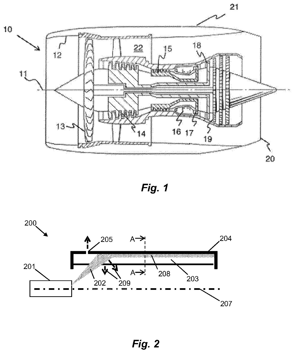
[0024]With reference to FIG. 1, a gas turbine engine is generally indicated at 10, having a principal and rotational axis 11. The engine 10 comprises, in axial flow series, an air intake 12, a propulsive fan 13, an intermediate pressure compressor 14, a high-pressure compressor 15, combustion equipment 16, a high-pressure turbine 17, an intermediate pressure turbine 18, a low-pressure turbine 19 and an exhaust nozzle 20. A nacelle 21 generally surrounds the engine 10 and defines both the intake 12 and the exhaust nozzle 20.

[0025]The gas turbine engine 10 works in the conventional manner so that air entering the intake 12 is accelerated by the fan 13 to produce two air flows: a first air flow into the intermediate pressure compressor 14 and a second air flow which passes through a bypass duct 22 to provide propulsive thrust. The intermediate pressure compressor 14 compresses the air flow directed into it before delivering that air to the high pressure compressor 15 where further comp...


PUM


Abstract

The present disclosure concerns an oil distribution assembly for a system having rotating components requiring a supply of oil, such as bearing components of a gas turbine engine. Example embodiments include an oil distribution assembly for a gas turbine engine, comprising: an oil distributor mounted for rotation about a rotation axis of the assembly and comprising an internal volume having a plurality of channels extending along an inner radial surface of the oil distributor; and an oil injector arranged to direct a supply of oil to the plurality of channels in a direction having a component in a first direction along the rotation axis; wherein each of the plurality of channels is angled relative to the rotation axis such that a radial distance between each channel and the rotation axis increases along the rotation axis.

Description

CROSS-REFERENCE TO RELATED APPLICATIONS[0001]This application is based upon and claims the benefit of priority from British Patent Application Number 1805180.5 filed 29 Mar. 2018, the entire contents of which are herein incorporated by reference.BACKGROUNDTechnical Field[0002]The present disclosure concerns an oil distribution assembly for a system having rotating components requiring a supply of oil, such as bearing components of a gas turbine engine.Description of the Related Art[0003]Oil distributors are commonly used within aerospace transmission systems to transport oil from one or more oil injectors (also known as oil injection jets) through to a rotating component to lubricate and cool components such as bearings, splines, gears and seals. Such oil distributers use centripetal force to retain oil on an internal rotating surface of the distributor. Structures such as slots, pockets and scallops may be used to achieve a particular desired flow and distribution of oil. The struc...

Claims


Application Information

Patent Timeline
Patent Type & Authority Patents(United States)
IPC IPC(8): B05B3/10F01D25/18F16C33/66
CPCB05B3/1021F01D25/18F16C33/6659F16C33/6677F05D2260/98
Inventor GREAVES, RICHARD
Owner ROLLS ROYCE PLC
Features
  • R&D
  • Intellectual Property
  • Life Sciences
  • Materials
  • Tech Scout
  • Unparalleled Data Quality
  • Higher Quality Content
  • 60% Fewer Hallucinations
Learn More