
Filter device

a filter device and filter technology, applied in the field of filter devices, can solve the problems of low acquisition cost of filter devices, low maintenance cost associated with filter replacement, low total operating cost, etc., and achieve the effect of simple and cost-effectiv

Active Publication Date: 2022-03-08
HYDAC PROCESS TECH
View PDF26 Cites 0 Cited by
  • Summary
  • Abstract
  • Description
  • Claims
  • Application Information

AI Technical Summary

Benefits of technology

The invention provides a filter device that can be made in a simple and cost-effective way. This is achieved by using identical filter inserts that can be produced through injection molding from low-cost materials like polyamides. The use of identical parts reduces the need for expensive tooling and makes maintenance and replacement easier and less expensive. The invention can help lower overall operating costs and make filter devices more accessible to a wider range of users.

Problems solved by technology

This results in low acquisition costs for the filter device and low maintenance costs associated with filter replacement, and thus, low total operating costs.

Method used


Image

  • Filter device
  • Filter device
  • Filter device

Examples


Embodiment Construction

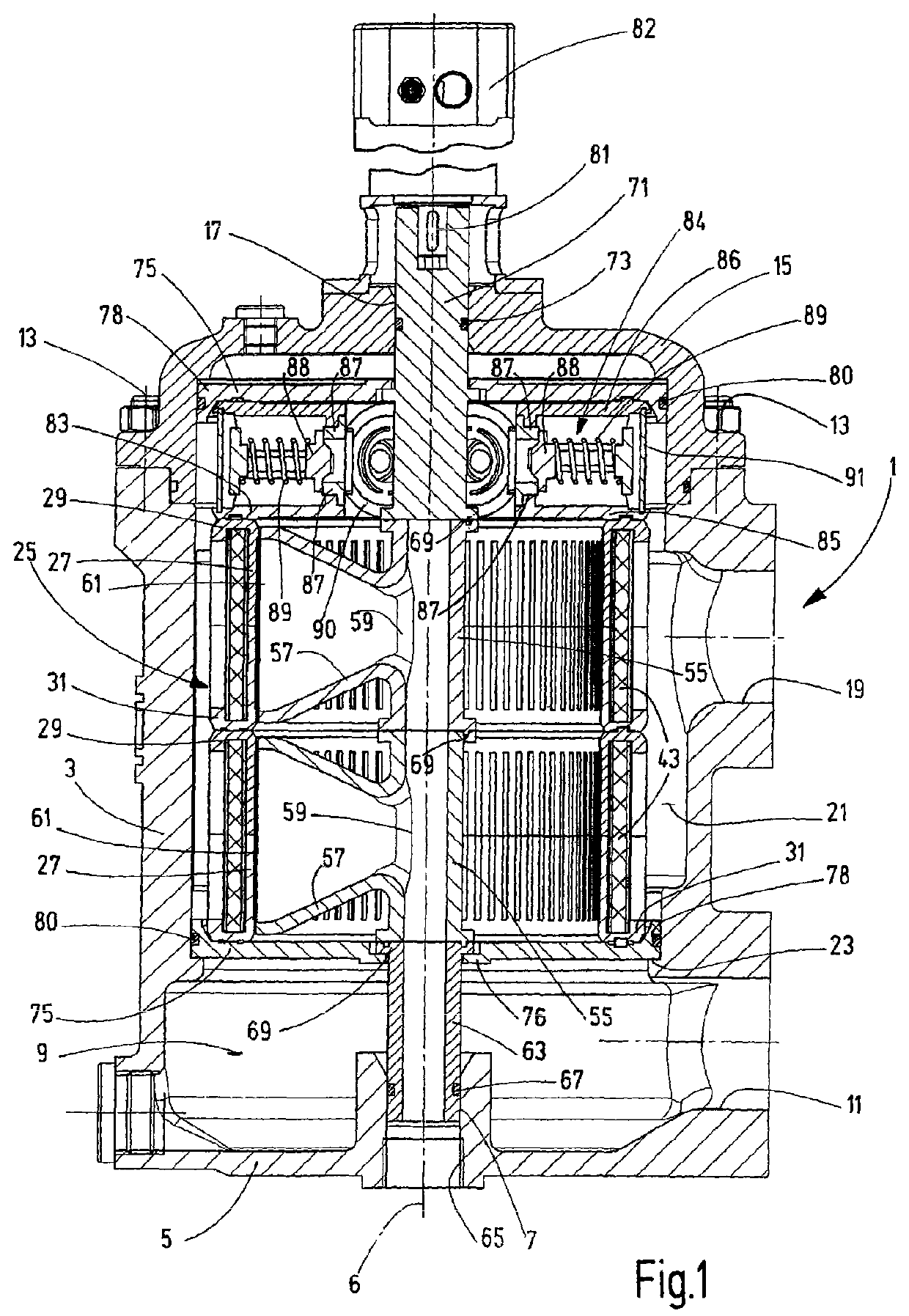
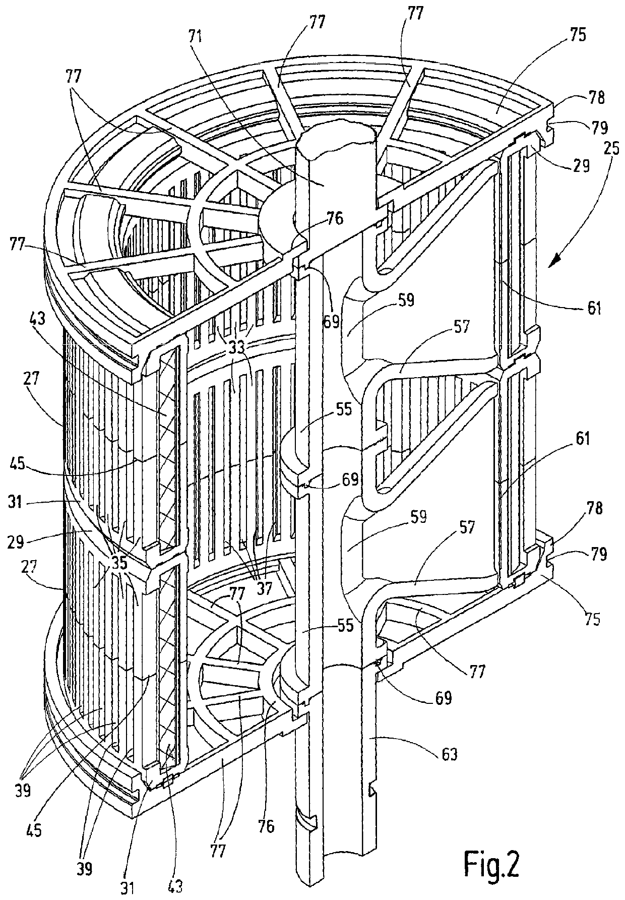
[0027]FIG. 1 shows an exemplary embodiment of the filter device according to the invention having a filter housing 1, which has a cup-shaped main housing part 3. At the base 5 of housing 1, a bearing point 7 is located coaxial to a central housing longitudinal axis 6. By way of access to the housing chamber 9, adjacent to the base 5 a side inlet 11 for the supply of unfiltered fluid is provided. The housing chamber 9 forms the dirty side. At the top, the main housing part 3 is closed by a housing cover 15 mounted in a removable manner by retaining screws 13, in which housing cover a bearing point 17 coaxial to the axis 6 is formed, just like in the base 5. In the main housing part 3, a filtered fluid outlet 19 is provided in the region of the housing cover 15. The filtered fluid outlet is arranged in a position aligned with the inlet 11 and outflows the filtered fluid from the adjacent housing chamber 21, which forms the clean side during operation. In the main housing part 3, above...


PUM

PropertyMeasurementUnit
pressureaaaaaaaaaa
volumesaaaaaaaaaa
angleaaaaaaaaaa

Abstract

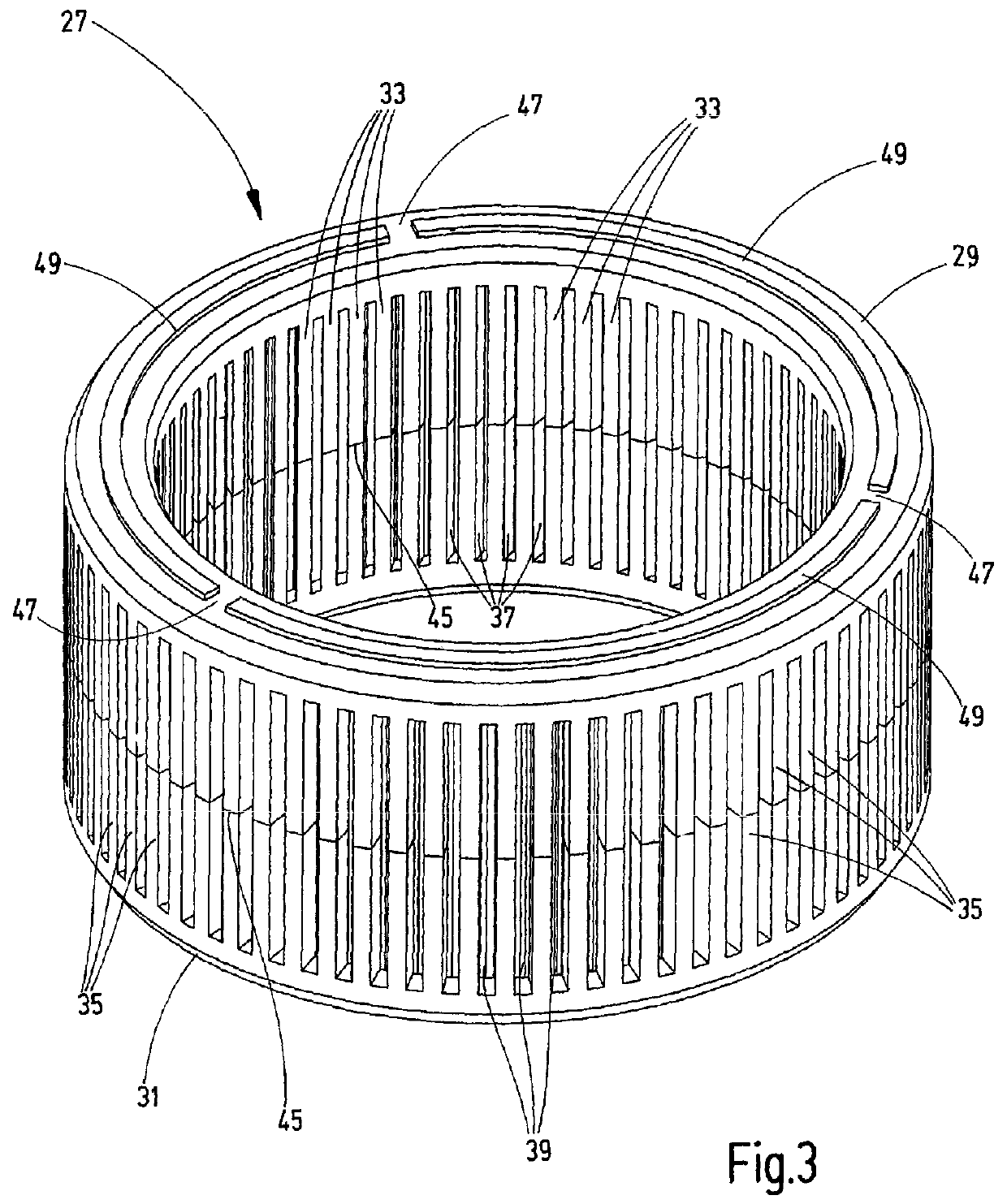
A filter device, in particular for lubricating oil filtration, includes at least two filter inserts (27), in each of which a filter material (43) is accommodated. The filter inserts are provided with fluid passage points (37, 39) and can be stacked on top of one another with the formation of a stack. A back-flushing device (55,57) is movably arranged along the inner side of the filter inserts (27). The individual filter inserts (27) are designed as identical parts at least with respect to their housings.

Description

FIELD OF THE INVENTION[0001]The invention relates to a filter device, in particular for the filtration of lubricating oil, having at least two filter inserts, in each of which a filter material is disposed. The filter inserts are provided with fluid passage points and can be stacked on top of one another, thereby forming a stacked structure. A backwash device, which is displaceably arranged along the inside of the filter inserts, is in the filter device.BACKGROUND OF THE INVENTION[0002]The integrity of lubricating oil is very important for the operational reliability and durability of internal combustion engines. In particular the continuous operation of diesel engines, which are operated using heavy oil, for instance in marine applications, puts particularly high demands on the condition of the lubricating oil. In such applications, the use of filter devices for the purification of lubricating oil is essential. In this regard the prior art specifies that filter devices are used in ...

Claims


Application Information

Patent Timeline
Patent Type & Authority Patents(United States)
IPC IPC(8): B01D29/54B01D29/23B01D29/68B01D29/58B01D29/94B01D35/00B01D35/147
CPCB01D29/232B01D29/23B01D29/54B01D29/58B01D29/682B01D29/688B01D29/94B01D35/005B01D35/147B01D2201/082B01D29/00
Inventor LINGEN, HANS-JUERGENKLEINKLEIN, RAPHAELBREINIG, MARKUS
Owner HYDAC PROCESS TECH
Learn More