Optomechanical pressure measurement system and method using the vibrational modes of a membrane

a pressure measurement system and membrane technology, applied in the field of pressure measurement systems, can solve the problems of high cost, inconvenient definition, and inability to accurately measure the pressure range of primary high-accuracy manometers, and achieve the effect of simple and robustness

Active Publication Date: 2022-03-29
UNIV OF MARYLAND
View PDF10 Cites 0 Cited by
  • Summary
  • Abstract
  • Description
  • Claims
  • Application Information

AI Technical Summary

Benefits of technology

[0029]It is therefore an object of the present invention to provide a mechanical damping gauge for high vacuum in range of 10−6 to 10−2 Pa, which is simple, robust, and sufficiently stable to operate as a sensor and a transfer standard.

Problems solved by technology

However, as pressure extends further and further below an atmosphere (deeper into the vacuum), this definition becomes inconvenient and impractical.
In this formulation, pressure metrology becomes a counting problem, specifically, counting particles in the vacuum by any available technique.
The primary high-accuracy manometers used in this pressure range also tend to be rather large, expensive, and require a high level of expertise to operate, and are thus usually owned and operated by national metrology institutes or sophisticated calibration laboratories.
Although these techniques have been the mainstay for UHV detection for several decades and many improvements have been made to make them more stable or to detect lower vacuum levels, they have not been completely satisfying for measuring total or partial pressures in the UHV or extreme-high vacuum (XHV) below 10−9 Pa for several reasons:(a) the heat generated by these gauges cause sufficient outgassing to change the pressure in a vacuum system;(b) the electron impact can “crack” molecules into fragments thus changing the chemical composition of the gas (a particular problem in partial pressure analysis);(c) the chemical composition can also be altered by chemical reactions on the hot filaments or other surfaces within the ionizer;(d) the ionization technique does not produce a primary sensor, i.e., an absolute sensor that does not require calibration;(e) additionally, electron-stimulated desorption (ESD) of ions from surfaces and the generation of X-rays due to electron impact on surfaces cause false signals.
This reduces the possibility of changing the chemical composition of the gas and outgassing in the system.
The vacuum requirements are a technical challenge in creating such devices.
The spinning rotor gauge has a zero-offset that disadvantageously is unpredictable to within about two orders of magnitude, roughly equivalent to a nitrogen pressure of 0.2 μPa to 10 mPa.
Further, the spinning rotor gauge has a disadvantage of inability to be a primary standard for pressure.
In addition, the spinning rotor gauge tends to be sensitive to external magnetic fields and orientation (tilt) of the device.

Method used


Image

  • Optomechanical pressure measurement system and method using the vibrational modes of a membrane
  • Optomechanical pressure measurement system and method using the vibrational modes of a membrane
  • Optomechanical pressure measurement system and method using the vibrational modes of a membrane

Examples


Embodiment Construction

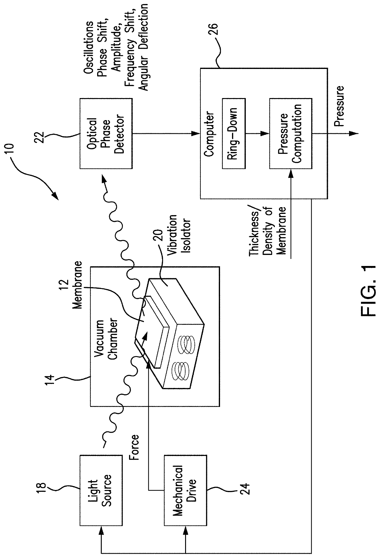
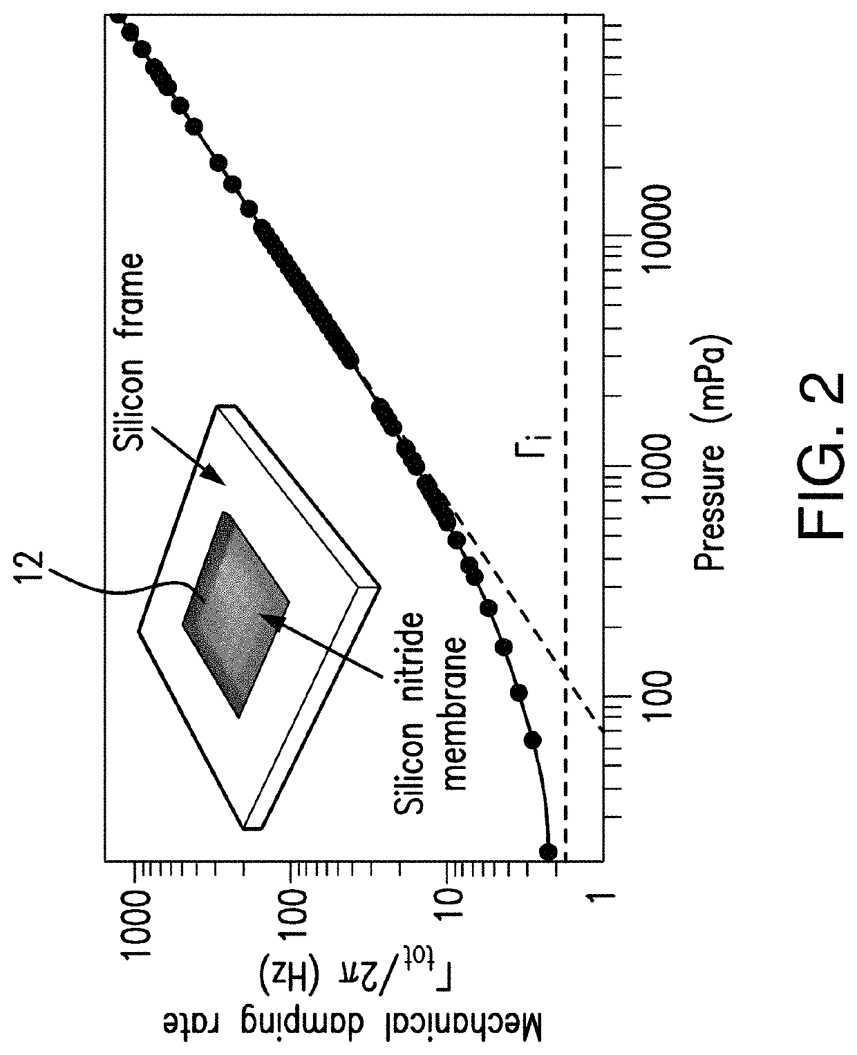
[0067]The subject pressure measuring system uses properties of the vibration modes excited in a membrane, for example, damping properties. Mechanical damping by drag forces may be used for a wide range of vacuum pressure sensors. The subject system relates to a class of oscillating mechanical resonators, which are desirable for pressure measurements because they may operate as absolute pressure sensors with high linearity, operate at high frequencies away from DC to minimize low frequency noise and drift, often allow for direct computation of pressure dependence from first principles, and do not generate large amounts of heat. The linear dynamic range is limited by intrinsic mechanical dissipation at low pressure, and the transition from molecular flow to viscous damping at high pressure.

[0068]The subject system demonstrates the ideal properties for pressure measurements, which include a low intrinsic mechanical dissipation and a mechanical element that is smaller than the mean free...


PUM

PropertyMeasurementUnit
pressureaaaaaaaaaa
pressureaaaaaaaaaa
pressureaaaaaaaaaa

Abstract

An optomechanical pressure-measurement system measures pressure in the range of 10−6 Pa-10−2 Pa by measuring various properties of a vibrational mode of an ultra-thin membrane member. With independent measurements of the thickness and density of the membrane, in addition to the measured vibration mode properties, the system can operate as a primary pressure sensor. The membrane member is mounted on a vibration-isolated mount and is excited by a drive force. A laser beam impinges on the excited membrane, and an optical phase detector detects the amplitude of the oscillations, as well as parameters of the laser beam affected by the membrane vibration. In one embodiment, a mechanical damping is computed based on the amplitude or frequency shift (depending on the pressure range), and the pressure based on the ring-down time of the membrane vibration mode.

Description

STATEMENT REGARDING FEDERAL SPONSORED RESEARCH OR DEVELOPMENT[0001]This invention is made with government support under 70NANB16H168 awarded by NIST. The government has certain rights in the invention.REFERENCE TO RELATED PATENT APPLICATION(S)[0002]This Utility Patent Application is based on a Provisional Patent Application Ser. No. 62 / 686,789 filed on 19 Jun. 2018.INCORPORATION BY REFERENCE[0003]The following article is incorporated by reference in its entirety: Julia Scherschligt, James A. Fedchak, Zeeshan Ahmed, Daniel S. Barker, Kevin Douglass, Stephen Eckel, Edward Hanson, Jay Hendricks, Nikolai Klimov, Thomas Purdy, Jacob Ricker, Robinjeet Singh, Jack Stone, ‘Quantum-based vacuum metrology at NIST’, in press at Journal of Vacuum Science and Technology B (2018).FIELD OF THE INVENTION[0004]The present invention is directed to a pressure measuring system, and more in particular, to a pressure measuring system capable of measuring high vacuum in the range of 10−6 to 10−2 Pa.[0005]...

Claims


Application Information

Patent Timeline
Patent Type & Authority Patents(United States)
IPC IPC(8): G01L1/10G01L27/00
CPCG01L1/103G01L1/106G01L27/005G01L21/22G01L9/0017
Inventor ECKEL, STEPHENFEDCHAK, JAMESPURDY, THOMASSINGH, ROBINJEET
Owner UNIV OF MARYLAND
Why Eureka
Try Eureka