Power converter

a power converter and converter technology, applied in the field of power converters, can solve the problems of reducing the degree of freedom and limited distance, and achieve the effects of reducing the loop inductance, and shortening the single run section

Active Publication Date: 2022-03-29
DENSO CORP
View PDF3 Cites 1 Cited by
  • Summary
  • Abstract
  • Description
  • Claims
  • Application Information

AI Technical Summary

Benefits of technology

[0014]According to the power converter of the present disclosure, at least one of the positive electrode bus bar and the negative electrode bus bar extends along the non-electrode surface of the capacitor element and then gather with each other, and thereafter run side by side in the bus bar parallel running section. According to this kind of bus bar arrangement, it is easy to shorten the single section of each bus bar in the process of the positive and negative electrode bus bars from the capacitor element toward the positive and negative power terminals. Also, according to this kind of bus bar arrangement method, even if the distance of the power semiconductor module with respect to the non-electrode surface is long, the bus bar parallel running section becomes long but the single running section does not becomes long. Therefore, it is possible to shorten the single run section without limiting the degree of freedom of the positional relationship between the power semiconductor module and the capacitor element. Moreover, in the bus bar parallel running section, since the electric current flowing through the positive bus bar and the electric current flowing through the negative bus bar face each other, the magnetic flux generated by these electric currents is canceled out. As a result, the effect of canceling out the inductance of

Problems solved by technology

However, the shortening of the distance is limited.
Furthermore, seeking a shortening of the distance in order to shorten the single running section may lead to a decre

Method used


Image

  • Power converter
  • Power converter
  • Power converter

Examples


first embodiment

1. First Embodiment

[0035]A first embodiment according to the present disclosure and modification examples thereof will be described with reference to FIGS. 1 to 6.

1-1. Configuration of Power Converter

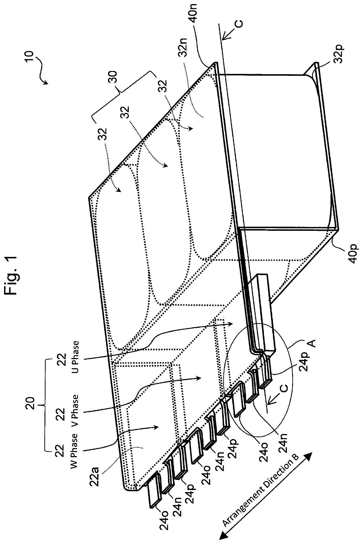
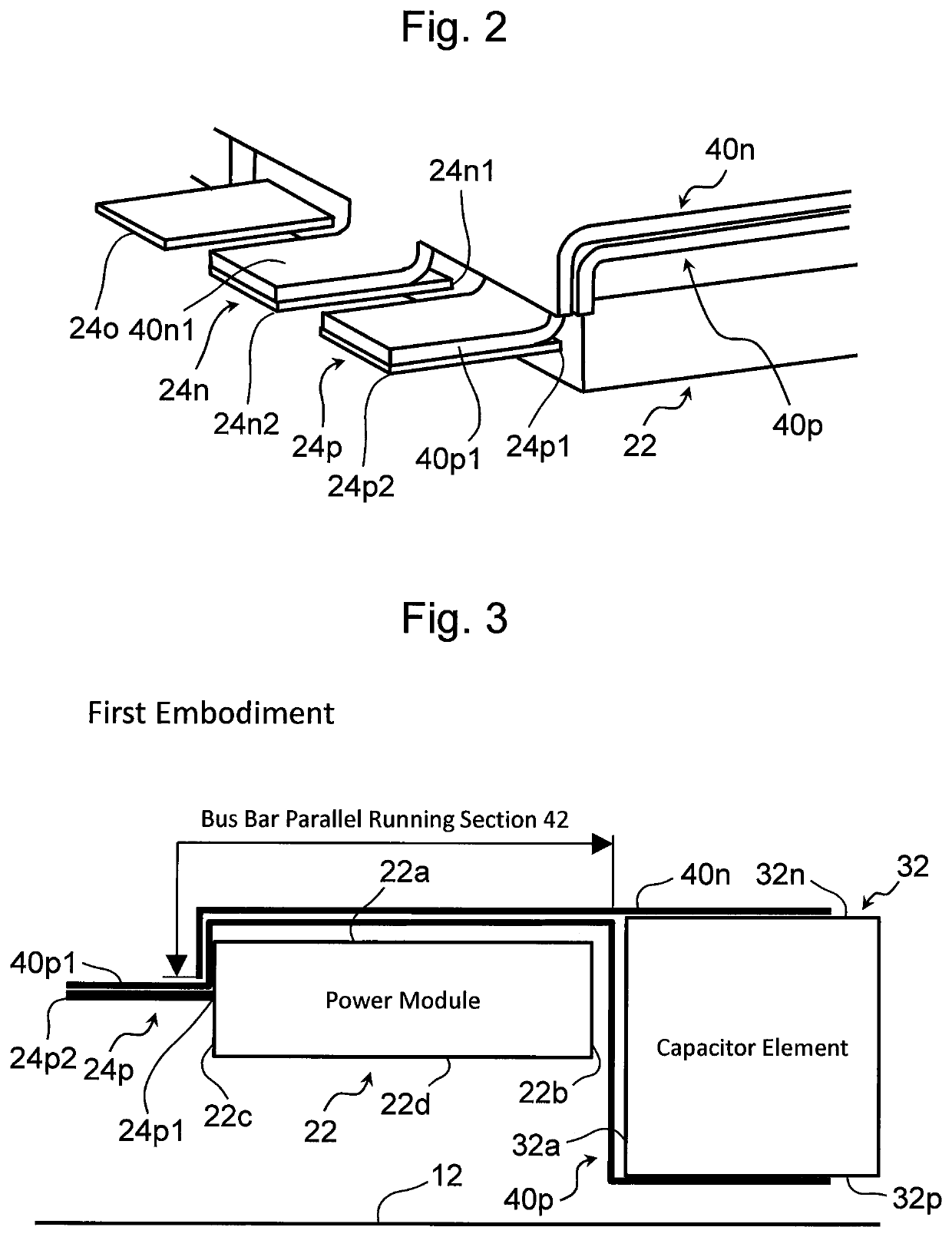
[0036]FIG. 1 is a perspective view showing a configuration of a main part of a power converter 10 according to the first embodiment. FIG. 2 is an enlarged view of a site A around power terminals 24p, 24n and 24o in FIG. 1. As an example, the power converter 10 is mounted on an electrified vehicle provided with a drive source including a motor generator (not shown).

[0037]The power converter 10 is provide with a power semiconductor unit 20, a capacitor unit 30, a positive electrode bus bar (also referred to as a “P bus bar”) 40p and a negative electrode bus bar (also referred to as a “N bus bar”) 40n. The P bus bar 40p and the N bus bar 40n each connects the power semiconductor unit 20 with the capacitor unit 30. These bus bars 40p and 40n are made of, for example, a conductive metal.

[003...

second embodiment

2. Second Embodiment

[0070]Then, a second embodiment according to the present disclosure will be described with reference to FIG. 7. FIG. 7 is a schematic diagram showing a feature of a power converter 50 according to the second embodiment. This power converter 50 is different from the power converter 10 according to the first embodiment in the following point.

[0071]Specifically, FIG. 7 shows a P bus bar 52p and an N bus bar 40n in the bus bar parallel running section 42. In the bus bar parallel running section 42 according to the present embodiment, the P bus bar 52p is in contact (more specifically, is in close contact) with the N bus bar 40n via an insulator 54. An example of the insulator 54 is electrically insulating paper. The insulator 54 corresponds to an example of the “first insulator” according to the present disclosure.

[0072]According to the configuration of the second embodiment described above, by minimizing the distance (clearance) between the P bus bar 52p and the N b...

third embodiment

3. Third Embodiment

[0073]Then, a third embodiment according to the present disclosure will be described with reference to FIG. 8. FIG. 8 is a schematic diagram showing a feature of a power converter 60 according to the third embodiment. The power converter 60 is different from the power converter 50 according to the second embodiment in the following points.

[0074]In the present embodiment, as shown in FIG. 8, a P bus bar 62p is in contact (more specifically, is in close contact) with the non-electrode surface 32a of the capacitor element 32 via an insulator 64. An example of the insulator 64 is also an electrically insulating paper. The insulator 64 corresponds to an example of the “second insulator” according to the present disclosure.

[0075]According to the configuration of the third embodiment described above, by minimizing the distance (clearance) between the P bus bar 62p and the non-electrode surface 32a, the effect of canceling out the magnetic flux due to the fact that the el...


PUM


Abstract

Positive and negative power terminals protrude from a power terminal arrangement surface not facing a capacitor element. Positive and negative electrode bus bars gather with each other after at least one of them extends along a non-electrode surface of the capacitor element, and then run side by side in a bus bar parallel running section. The positive electrode bus bar runs in parallel with the negative electrode bus bar in the bus bar parallel running section, and then extends along the positive power terminal from the proximal end of the positive power terminal to the distal end thereof. The negative electrode bus bar runs in parallel with the positive electrode bus bar in the bus bar parallel running section, and then extends along the negative power terminal from the proximal end of the negative power terminal to the distal end thereof.

Description

CROSS-REFERENCE TO RELATED APPLICATION[0001]The present disclosure claims priority under 35 U.S.C. § 119 to Japanese Patent Application No. 2019-203394, filed on Nov. 8, 2019. The content of which is incorporated herein by reference in its entirety.BACKGROUNDTechnical Field[0002]The present disclosure relates to a power converter.Background Art[0003]For example, JP 2014-121121 A discloses a power converter including a power semiconductor module, and a capacitor element connected to the power semiconductor module via a DC-side bus bar.SUMMARY[0004]FIG. 15 is a schematic diagram showing the structure (prior art) of a power converter disclosed in JP 2014-121121 A in a simplified manner. In the structure shown in FIG. 15, a positive power terminal and a negative power terminal of a power semiconductor module is disposed on a module surface located on the side facing a capacitor element. Also, these power terminals are connected to the capacitor element via a positive electrode bus bar a...

Claims


Application Information

Patent Timeline
IPC IPC(8): H02M7/537H02M7/00H02M1/12
CPCH02M7/003H02M1/12H02M7/537H02M7/48H05K7/20927H02M7/5387
Inventor AOYAGI, SHINSUKEIWATA, SHUICHIKISHIMOTO, NAOYUKI
Owner DENSO CORP
Why Eureka
Try Eureka