
Thin-film piezoelectric actuator

a piezoelectric actuator and thin film technology, applied in the direction of piezoelectric/electrostrictive/magnetostrictive devices, electrical apparatus, printing, etc., can solve the problems of inability to accurately control the change amount of the chamber volume, the reliability of the device, and the edge of the chamber where the undesired displacement is detected, so as to reduce the displacement sensitivity to driving voltage, eliminate undesired displacement of the piezoelectric actuator, and efficiently actu

Active Publication Date: 2022-04-05
SAE MAGNETICS (HK) LTD
View PDF12 Cites 0 Cited by
  • Summary
  • Abstract
  • Description
  • Claims
  • Application Information

AI Technical Summary

Benefits of technology

The design effectively eliminates undesired displacements and increases displacement sensitivity, leading to improved precision and reliability in actuating the vibration plate, particularly in inkjet and other MEMS applications.

Problems solved by technology

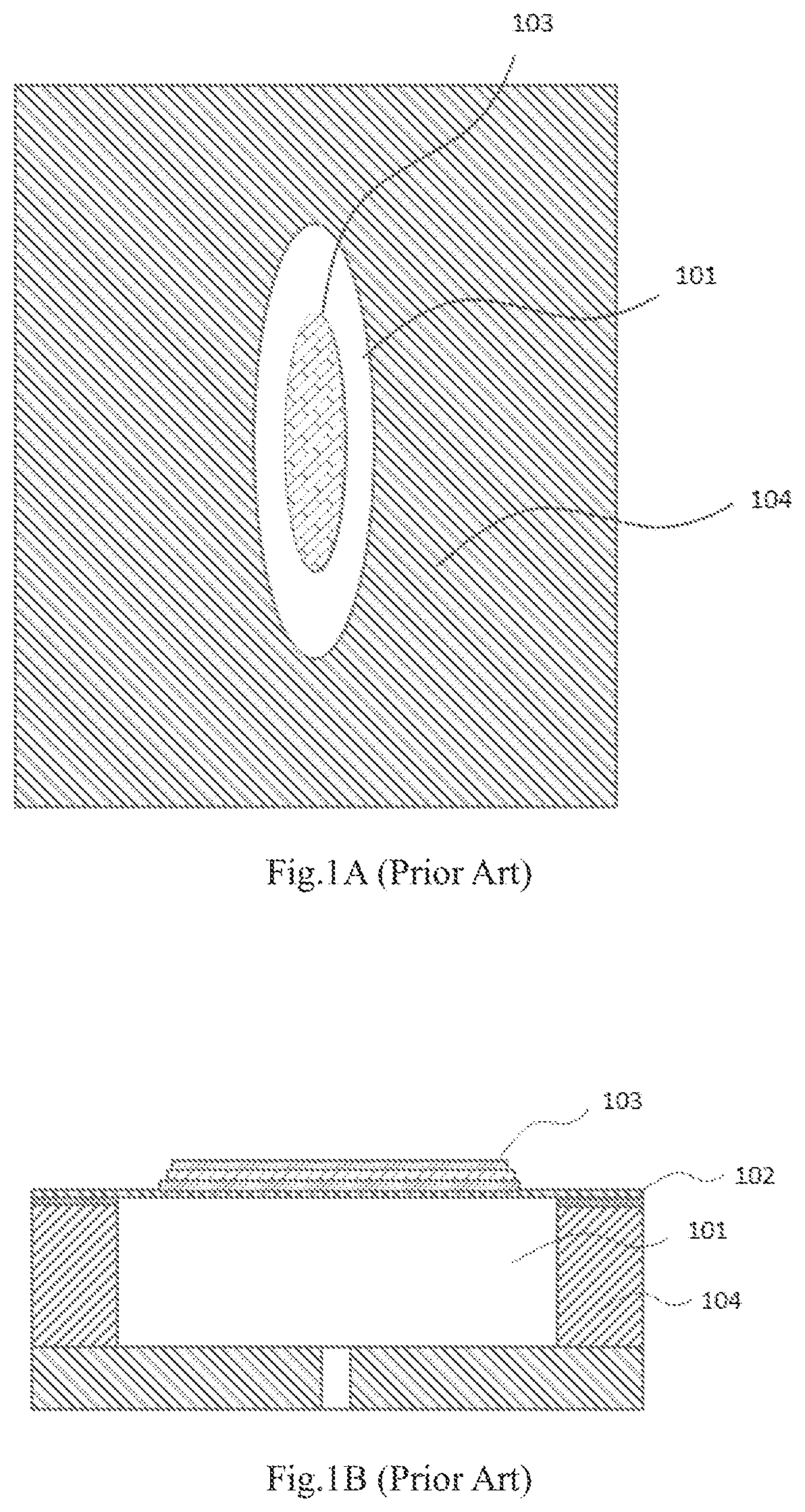
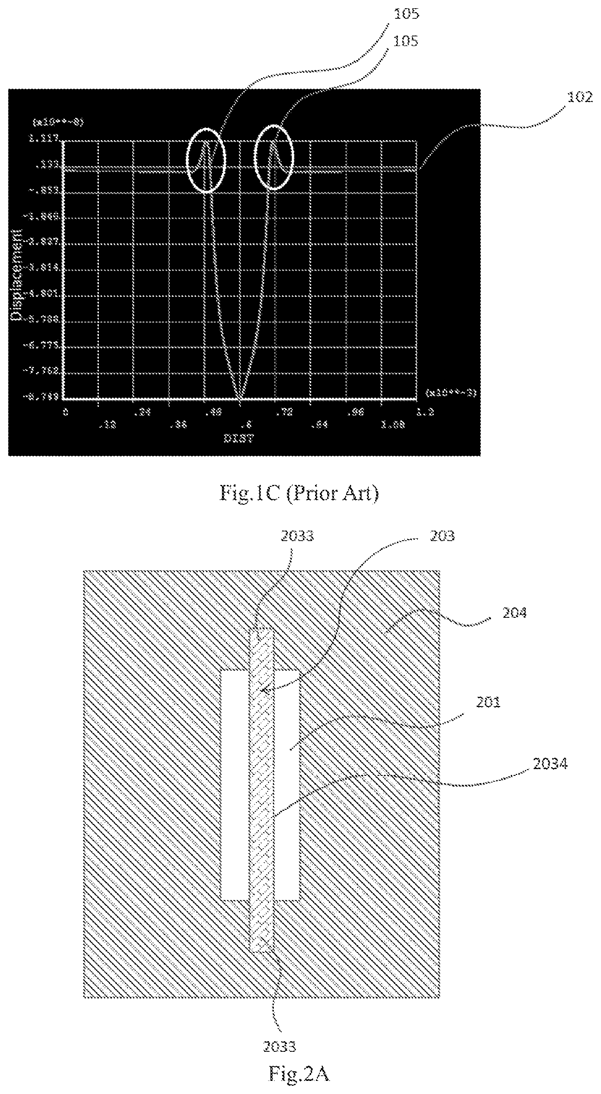
However, in existing devices with such structure, undesired displacements in the opposite direction at the edge of the chamber are detected.
Such undesired displacements can affect the reliability of the device, make it difficult to achieve precise control of the change amount of the chamber volume, and disturb the accuracy of both ink jetting position and ink jetting amount.

Method used


Image

  • Thin-film piezoelectric actuator
  • Thin-film piezoelectric actuator
  • Thin-film piezoelectric actuator

Examples


Embodiment Construction

[0033]Technical solutions according to various embodiments of the present invention will be clearly and completely described in conjunction with the accompanying drawings illustrating particular embodiments of the present invention.

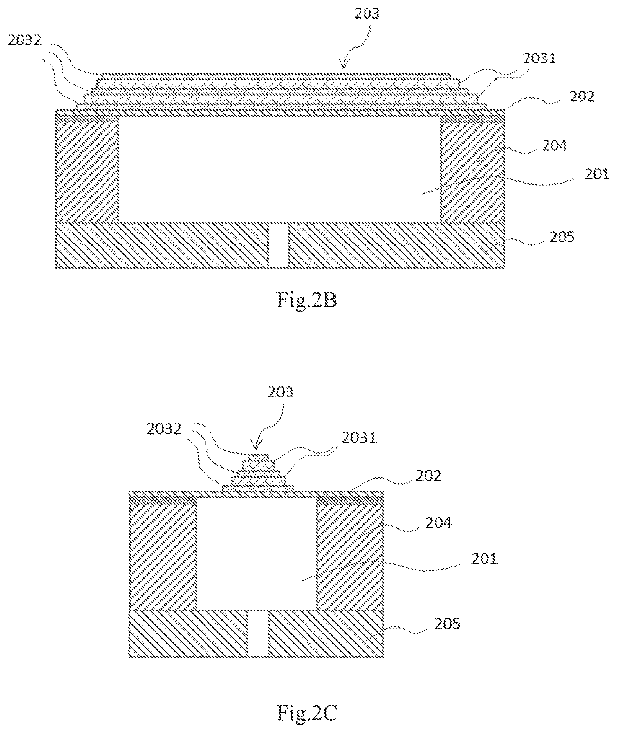
[0034]Referring to FIGS. 2A, 2B, 2C and FIGS. 3-4, a piezoelectric device according to an embodiment of the present invention comprises a pressure chamber forming layer (204, 304, 404), a vibration plate (202) disposed on and connected with the pressure chamber forming layer (204, 304, 404) to form a pressure chamber (201, 301, 401), and a piezoelectric element (203, 303, 403) which is disposed on the vibration plate (202) and used for driving the vibration plate to move and thus changing a volume of the pressure chamber.

[0035]Herein, the piezoelectric element (203, 303, 403) is disposed on the vibration plate (202, 302, 402) in such a manner as to cover a portion of the pressure chamber (201, 301, 401), wherein the piezoelectric element (203, 303, 403) h...


PUM


Abstract

A piezoelectric device comprises a pressure chamber forming layer, a vibration plate disposed on and connected with the pressure chamber forming layer to form a pressure chamber, and a piezoelectric element disposed on the vibration plate and used for driving the vibration plate to move and thus changing a volume of the pressure chamber, wherein the piezoelectric element is disposed on the vibration plate in such a manner as to cover a portion of the pressure chamber, the piezoelectric element has two opposite ends respectively extending beyond an edge of the pressure chamber and covering the pressure chamber forming layer. The piezoelectric device of the present invention can efficiently actuate the vibration plate, eliminate undesired displacements of the vibration plate in the opposite direction at the edge of the chamber, and provide higher displacement sensitivity to driving voltage.

Description

[0001]This application is the U.S. national phase of International Application No. PCT / CN2017 / 093064 filed Jul. 15, 2017 which designated the U.S. and the entire contents of which are hereby incorporated by reference.FIELD OF THE INVENTION[0002]The present invention relates to a piezoelectric device and more particularly to a thin film piezoelectric actuator for MEMS (Micro Electro Mechanical System) membrane structure.BACKGROUND OF THE INVENTION[0003]Piezoelectric elements are widely used as drive elements and applied in various fields such as MEMS structure inkjet, micro pump, micro mirror and PMUT (Piezo Micromachined Ultrasonic Transducer), because the piezoelectric elements may be deformed when an electrical field is applied.[0004]For example, a vibration plate of an inkjet printing head may constitute a part of a wall of an ink chamber, and the ink chamber may be in communication with a nozzle orifice that ejects ink droplets. In the case that a thin film piezoelectric element...

Claims


Application Information

Patent Timeline
Patent Type & Authority Patents(United States)
IPC IPC(8): B41J2/14H01L41/047H01L41/09H10N30/20H10N30/87
CPCB41J2/14233H01L41/047H01L41/0973B41J2002/14241B41J2002/14491B41J2002/14258B41J2202/11H10N30/50H10N30/2047H10N30/87
Inventor XIONG, WEIHE, FEIIIJIMA, ATSUSHI
Owner SAE MAGNETICS (HK) LTD
Learn More