System for measuring at least one physical characteristic for a tyre assembly

a technology of tyre assembly and physical characteristic, applied in the direction of tyre measurement, vehicle components, transportation and packaging, etc., can solve the problems of not being able to adapt to smaller rims, unable to monitor pressure on rims which are too small, and not being able to drive vehicles

Active Publication Date: 2022-04-19
KEMLAIR
View PDF7 Cites 0 Cited by
  • Summary
  • Abstract
  • Description
  • Claims
  • Application Information

AI Technical Summary

Benefits of technology

[0006]The aim of the invention is in particular to provide a new type of system for measuring at least one physical characteristic such as pressure and / or temperature for a pneumatic assembly, the compactness of which allows it to be adapted even to pneumatic assemblies with very small rims and the simplicity of which makes it possible to reduce manufacturing costs while maintaining performance equivalent to current devices for monitoring the pressure of pneumatic assemblies of passenger vehicles.
[0007]To this end, the invention relates to a system for measuring at least one physical characteristic for a pneumatic assembly, comprising a device for detecting the physical characteristic, a device for wireless transmission of values representing the measurements obtained by the detection device, a one-way fluid passage device for inflating the pneumatic assembly, and an electrical energy source, characterized in that the measuring system comprises an electrically conductive metal body closed by a cover made of material transparent to the waves of the wireless transmission device, allowing the body to be used as a receptacle which provides for stable positioning, the transmission of electrical energy, and the mechanical protection of the devices of the measuring system while allowing wireless transmission through the cover of values representing the measurements obtained by the detection device.
[0010]Finally, the body is preferably used as an element for transmitting electrical energy between the electrical energy source and the devices of the measuring system. Some of the electrical connections can therefore be established by the body itself in this way. The measuring system thus has fewer components and is therefore more compact and more economical to manufacture.
[0015]Preferably, according to the invention, at least one part of the antenna is surrounded by the body and at least one other part is surrounded by the cover. The dimensions and positioning of the body and of the antenna, in particular with respect to one another, i.e. in particular the penetration of the antenna into the body, make it possible to optimize the quality of the emission of the wireless transmission device. The part of the antenna surrounded by the body thus preferably extends over a height of less than or equal to 7 mm. The antenna can be mounted around the electronics of the measuring system in order to provide the highest possible maximum antenna height, i.e. the part of the antenna surrounded by the cover can extend near the cover, or even be placed against a face of the cover or embedded in the cover, i.e. can be inaccessible without breaking the cover.
[0021]According to a first embodiment, the rim is rigidly connected between the body and the fixing device while allowing inflation of the pneumatic assembly by the measuring system. This installation is preferred when the geometry of the rim imposes a bend on the one-way fluid passage device allowing inflation of the pneumatic assembly, i.e. prevents its exit in a straight line.

Problems solved by technology

These devices are not yet compulsory for motorized cycles, i.e. vehicles with two or three wheels such as motorcycles, mopeds, or three-wheeled motorcycles (sometimes called “trikes”).
Such adaptations to smaller rims may not be possible because the plastic housings of the monitoring devices used for passenger vehicles are too large, which makes pressure monitoring impossible for rims which are too small.

Method used


Image

  • System for measuring at least one physical characteristic for a tyre assembly

Examples


first embodiment

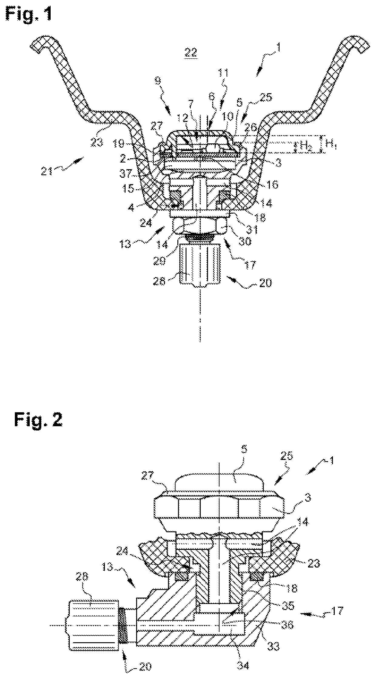
[0046] shown in FIG. 1, the one-way fluid passage device 13 is located in the lower part of the body 3. The device 13 essentially comprises at least one channel 14 and a nonreturn valve 20 for inflating the pneumatic assembly 21 and preventing the deflation of said assembly. Since the valve 20 is of a conventional type for a vehicle pneumatic assembly valve 21, it will not be described in any more detail below. In the example in FIG. 1, the nonreturn valve 20 is capped with a protective cap 28.

[0047]According to the first embodiment shown in FIG. 1, the fixing device 17 makes it possible to fasten the body 3 in a recess 24 of the rim 23 in order to rigidly connect the pneumatic assembly 21 to the measuring system 1 of the invention. As can be seen in FIG. 1, the fixing device 17 may comprise at least one sealing element 18 (located between the body 3 and the rim 23 in the example in FIG. 1) intended to ensure maintenance of the pressure of the interior space 22 of the pneumatic asse...

second embodiment

[0049]A second embodiment shown in FIG. 2 is provided, for example, when it is undesirable for the one-way fluid passage device 13 to be a rectilinear extension of the body 3 of the measuring system 1. This installation can be used e.g. when the geometry of the rim 23 imposes a bend on the one-way fluid passage device 13 allowing inflation of the pneumatic assembly, i.e. prevents its exit in a straight line.

[0050]As shown in FIG. 2, the second embodiment comprises a second body 33 attached to a body 3 similar to the first embodiment but truncated from part of its lower region. It is also better visible in FIG. 2 that the body 3 may have at least one shape (flat portions below the lip 27 in the manner of the outer surface of a nut in the case of FIG. 2) intended to improve its grip. The one-way fluid passage device 13 is located in the second body 33. The device 13 essentially comprises at least one second channel 34 and a nonreturn valve 20 for inflating the pneumatic assembly 21 an...


PUM


Abstract

The invention relates to a system (1) for measuring at least one physical characteristic for a pneumatic assembly (21), comprising a device (9) for detecting the physical characteristic, a device (11) for wireless transmission of values representing the measurements obtained by the detection device (9), a one-way fluid passage device (13) for inflating the pneumatic assembly (21), and a source (15) of electrical energy. According to the invention, the measuring system (1) comprises an electrically conductive metal body (3) closed by a cover (5) made of material transparent to the waves of the wireless transmission device (11), allowing the body (3) to be used as a receptacle which provides for stable positioning, the transmission of electrical energy, and the mechanical protection of the devices (9, 11) of the measuring system (1) while allowing wireless transmission through the cover (5) of values representing the measurements obtained by the detection device (9).

Description

RELATED APPLICATIONS[0001]The present application is a national phase filing under 35 USC 371 of International Application No. PCT / EP2020 / 052301, filed on Jan. 30, 2020, which claims priority to France Application No. 1901286, filed on Feb. 8, 2019, the entire contents and disclosures of which are hereby incorporated by reference.TECHNICAL FIELD OF THE INVENTION[0002]The invention relates to a system for measuring at least one physical characteristic, such as pressure and / or temperature, for a pneumatic assembly, which allows the monitoring of the operating state of the pneumatic assembly. The measuring system according to the invention is particularly suitable for pneumatic assemblies intended for vehicles with two or three wheels, whether they are motorized or not.TECHNICAL BACKGROUND OF THE INVENTION[0003]Devices for monitoring the pressure of pneumatic assemblies, which are now legally required in certain locations, are already known in the field of passenger vehicles. These kno...

Claims


Application Information

Patent Timeline
Patent Type & Authority Patents(United States)
IPC IPC(8): B60C23/04
CPCB60C23/0408B60C23/0498B60C23/0494
Inventor KEMPF, CHRISTIAN
Owner KEMLAIR
Why Eureka
Try Eureka