Heat pump system for producing steam by using recuperator
a heat pump and recuperator technology, which is applied in the direction of heat pumps, steam generation using hot heat carriers, steam separation arrangements, etc., can solve the problems of limited heat exchange amount of the condenser, and the quality of the refrigerant introduced into the evaporator can be minimized, the steam production efficiency can be improved, and the condenser heat can be increased.
- Summary
- Abstract
- Description
- Claims
- Application Information
AI Technical Summary
Benefits of technology
Problems solved by technology
Method used
Image
Examples
first embodiment
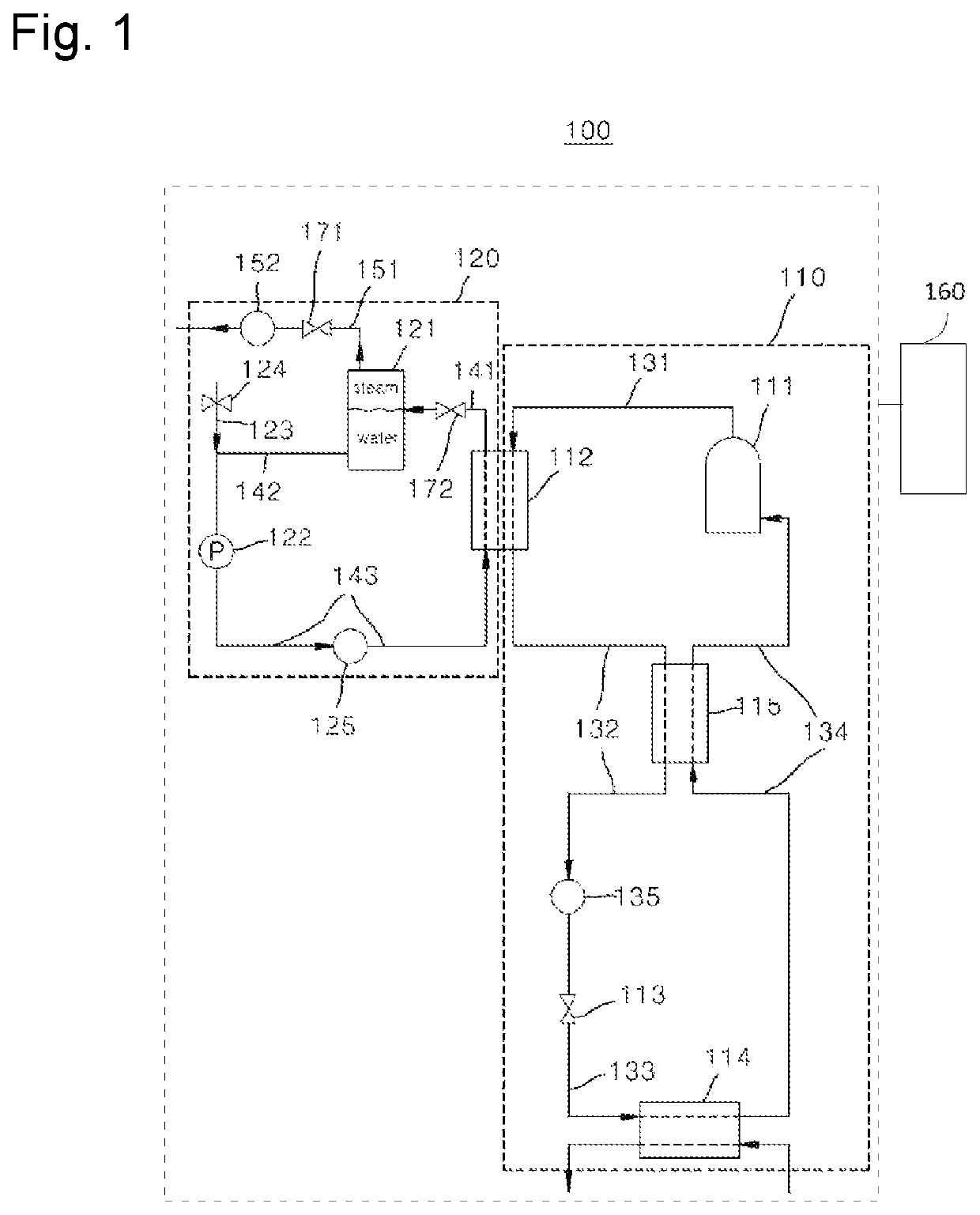
[0020]FIG. 1 is a view illustrating the schematic configuration of a heat pump system for producing steam according to the present invention.
[0021]Referring to FIG. 1, a heat pump system 100 for producing steam according to the first embodiment of the present invention includes a refrigerant cycle 110, a steam producing cycle 120, and a controller 160.
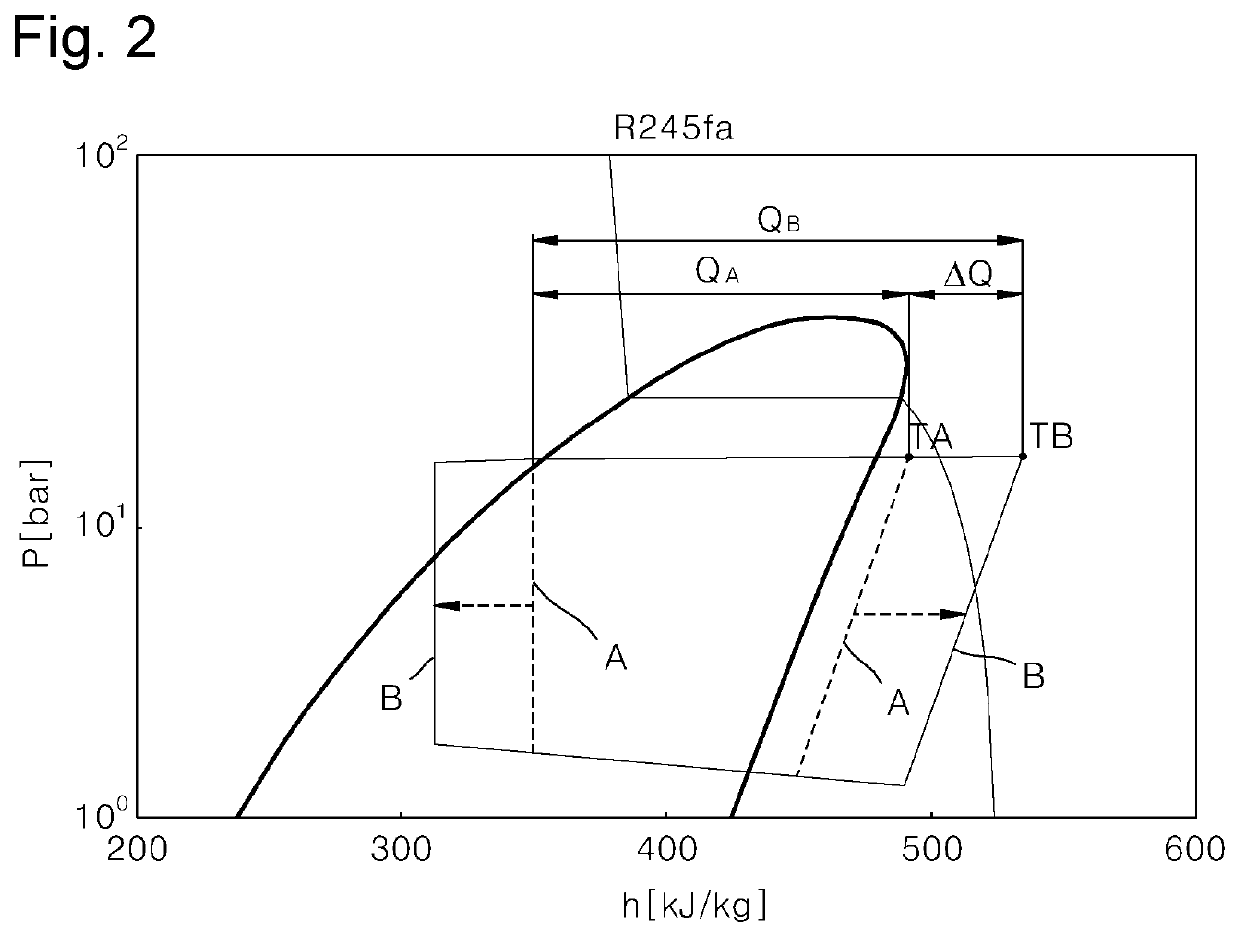
[0022]The refrigerant cycle 110 is a cycle in which a refrigerant circulates. An example in which R245fa is used as the refrigerant, will be described.
[0023]The refrigerant cycle 110 includes a compressor 111, a condenser 112, an expansion device 113, an evaporator 114, and a recuperator 115.
[0024]The compressor 111 compresses the refrigerant that circulates in the refrigerant cycle 110. The compressor 111 and the condenser 112 are connected to each other via a first refrigerant flow path 131. The compressor 111 is an inverter compressor.
[0025]The condenser 112 condenses the refrigerant generated in the compressor 111. The condenser 11...
second embodiment
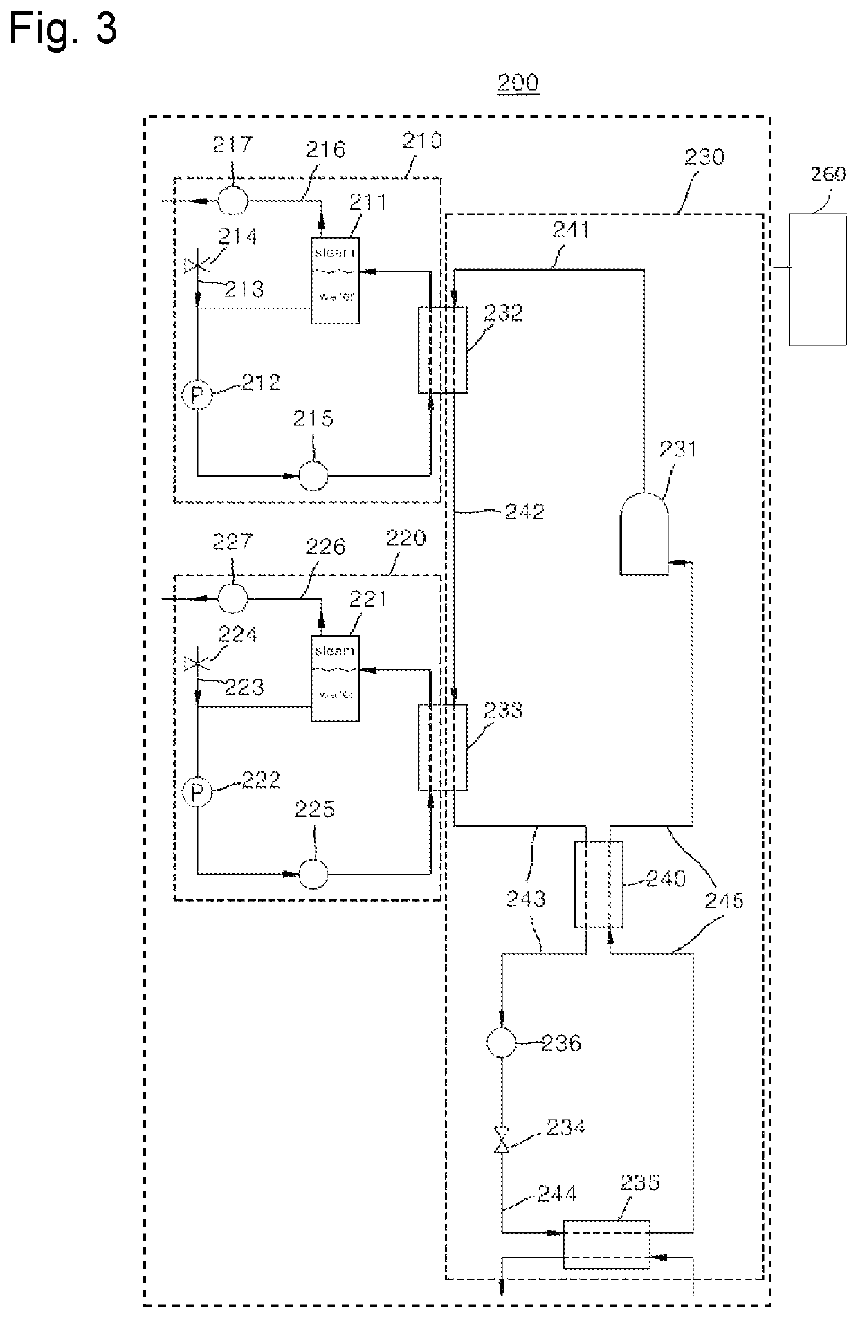
[0066]FIG. 3 is a view illustrating the configuration of a heat pump system for producing steam according to the present invention. FIG. 4 is a p-h diagram of a refrigerant cycle illustrated in FIG. 3.
[0067]Referring to FIGS. 3 and 4, a heat pump system 200 for producing steam according to the second embodiment of the present invention is different from the first embodiment in that the heat pump system 200 for producing steam according to the second embodiment includes one refrigerant cycle 230 and first and second steam producing cycles 210 and 220, a refrigerant compressed by a compressor 231 of the refrigerant cycle 230 passes through a heat exchanger 232 and a condenser 233 sequentially and the first steam producing cycle 210 receives a heat source from the heat exchanger 232 and the second steam producing cycle 220 receives a heat source from the condenser 233, and the remaining features and effects thereof are similar and thus, only different features will be described in deta...
third embodiment
[0121]FIG. 5 is a view illustrating the configuration of a heat pump system for producing steam according to the present invention.
[0122]Referring to FIG. 5, a heat pump system 300 for producing steam according to the third embodiment of the present invention is different from the second embodiment in that a compressor discharge flow path 310 on which a refrigerant compressed by a compressor 231 is discharged, is diverged into a heat exchanger supply flow path 311 and a heat exchanger bypass flow path 312, a three way valve 313 is installed at a point where the compressor discharge flow path 310 is diverged into the heat exchanger supply flow path 311 and the heat exchanger bypass flow path 312 and the flow rate of the refrigerant supplied to a heat exchanger 232 and the condenser 233 can be controlled, and the remaining features and effects thereof are similar and thus, a detailed description thereof will be omitted.
[0123]Also, a temperature sensor 320 for measuring the temperature...
PUM
 Abstract
Description
Claims
Application Information
 - R&D
- Intellectual Property
- Life Sciences
- Materials
- Tech Scout
- Unparalleled Data Quality
- Higher Quality Content
- 60% Fewer Hallucinations
Browse by: Latest US Patents, China's latest patents, Technical Efficacy Thesaurus, Application Domain, Technology Topic, Popular Technical Reports.
© 2025 PatSnap. All rights reserved.Legal|Privacy policy|Modern Slavery Act Transparency Statement|Sitemap|About US| Contact US: help@patsnap.com


