Fluid compressor

a fluid compressor and compressor technology, applied in the direction of bearings, engine fuctions, dynamo-electric machines, etc., can solve the problems of waste of heat from cooling liquid, compressors are very bulky, and cannot be integrated in a limited environment, so as to achieve compact compressors, save space, and high rotational speed

Active Publication Date: 2022-04-26
BELENOS CLEAN POWER HLDG
View PDF27 Cites 0 Cited by
  • Summary
  • Abstract
  • Description
  • Claims
  • Application Information

AI Technical Summary

Benefits of technology

[0010]It is another object of the invention to provide a two-stage, high-speed fluid compressor having a high rotational speed, a high compression ratio and optimum energy efficiency, yet which occupies a small volume.
[0013]Thus, the compressor according to the invention includes one and the same fluid both for compression and for cooling the compressor. The arrangement of channels used both for circulating fluid to be compressed and for cooling the various compressor elements makes it possible to obtain a very compact compressor. In particular, the configuration with the electronic component cooled via the inner wall has several advantages compared to a configuration wherein the electronic component is cooled directly by the fluid. All the electronic components can be arranged without special sealing. It is possible to carry out work on the electronic components without draining the fluid, which is a complicated and expensive operation. Further, securing the electronic component inside the integrated housing in the case saves space.
[0014]Moreover, the compressor according to the invention makes it possible to recover all heat losses in the motor, in the bearings supporting the motor shaft and in the electronic components, to transform said losses into useful work. Thus, the compressor according to the invention has a high rotational speed, a high compression ratio and optimum energy efficiency, while occupying a small volume.

Problems solved by technology

Indeed, the high speed rotation of the motor causes very high heating, such that the compressor elements must be cooled to avoid damage.
Consequently, these compressors are very bulky and cannot be integrated in a limited environment.
Further, the heat recovered by the cooling liquid is wasted, which constitutes a considerable waste of energy.

Method used


Image

  • Fluid compressor
  • Fluid compressor
  • Fluid compressor

Examples


case 2

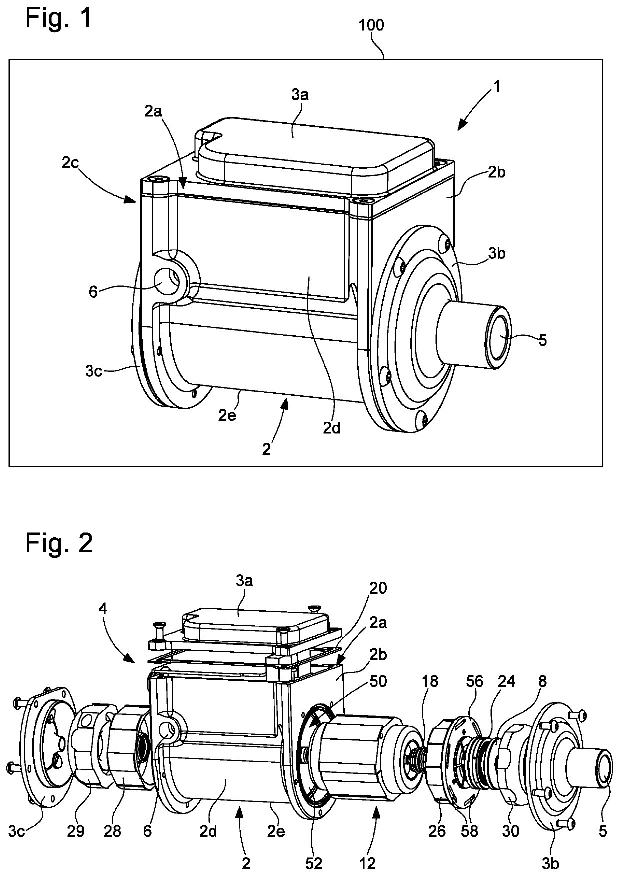
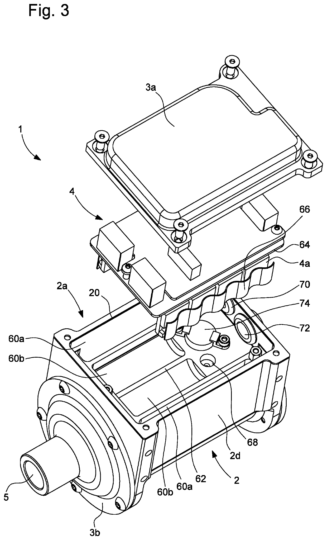
[0028]Case 2 has an inlet 5 for fluid to be compressed arranged on front cover 3b and a tangential compressed fluid outlet 6 arranged on one of lateral faces 2d of case 2.

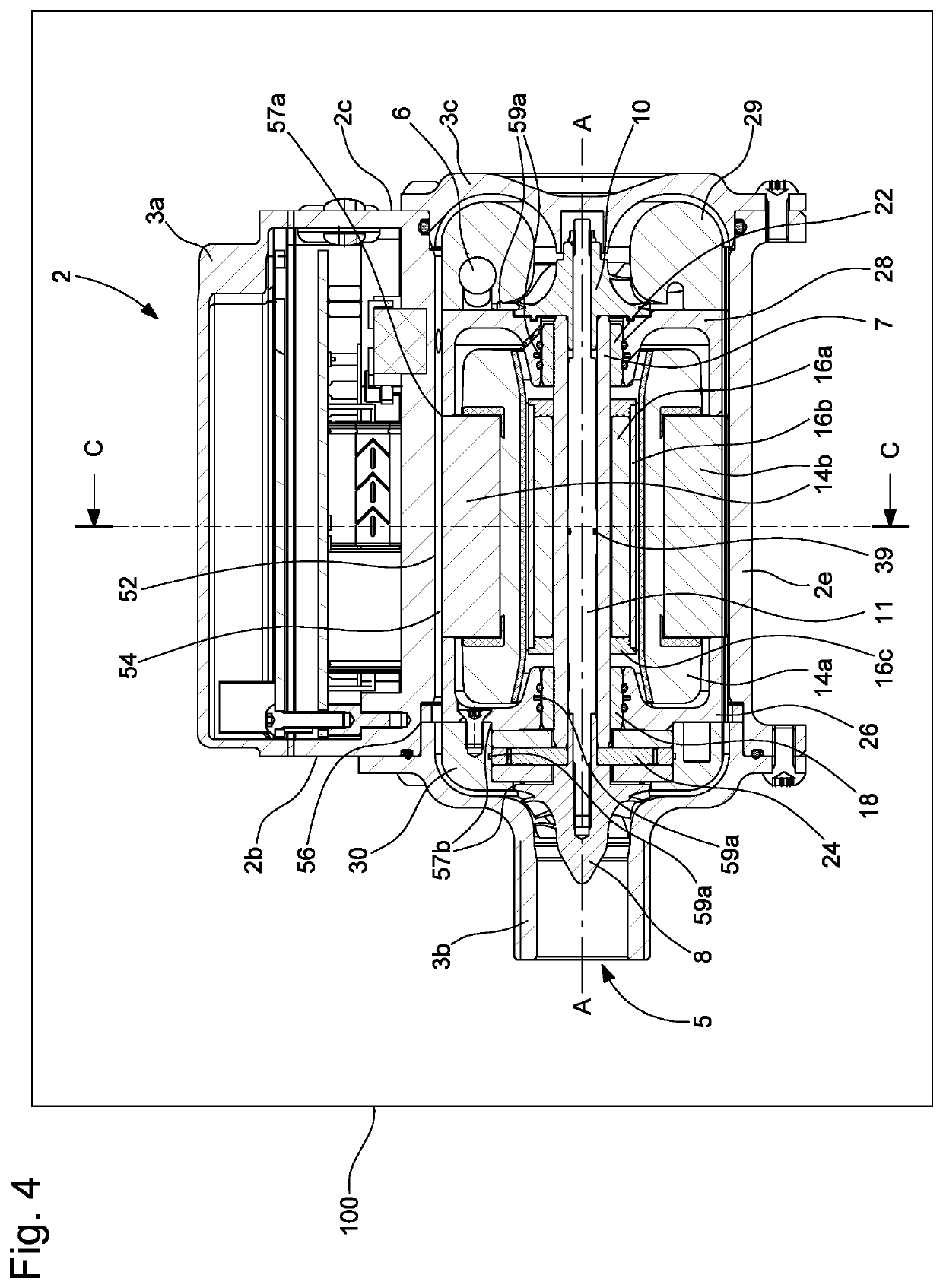
[0029]Referring to FIG. 4, case 2 contains a ceramic shaft 7, rotatably mounted about a longitudinal axis AA passing through front and back faces 2b and 2c, a first centrifugal compression wheel 8 and a second centrifugal compression wheel 10 mounted back-to-back at each end of shaft 7, said first compression wheel 8 forming a first compression stage and said second compression wheel 10 forming a second compression stage. More particularly, shaft 7 is hollow and contains a threaded rod 11, at each end of which is screwed one of compression wheels 8, 10, which allows for easy assembly and disassembly of the compression wheels. Thus, the two compression wheels 8 and 10 are driven on the same shaft 7, which provides better energy efficiency and avoids using a reduction gear. The back of compression wheels 8 and 10 inc...


PUM


Abstract

A two-stage, high speed fluid compressor including a case having a fluid inlet and a compressed fluid outlet and containing a shaft rotatably mounted about a longitudinal axis, a first compression wheel and a second compression wheel mounted back-to-back on the shaft, the first compression wheel forming a first compression stage and the second compression wheel forming a second compression stage, and a motor positioned between the first compression wheel and the second compression wheel and arranged to rotate the shaft. The case includes an inner through housing inside which is arranged at least the motor, the inner housing having an inner wall arranged to form, with the motor, channels between at least the inner wall and the motor, the channels extending to cool the motor in contact with the fluid flowing in the channels.

Description

CROSS-REFERENCE TO RELATED APPLICATION[0001]This application claims priority to European Patent Application No. 18168587.6 filed on Apr. 20, 2018, the entire disclosure of which is hereby incorporated herein by reference.FIELD OF THE INVENTION[0002]The present invention relates to a two-stage, high speed fluid compressor comprising a case having a fluid inlet and a compressed fluid outlet and containing a shaft rotatably mounted about a longitudinal axis, a first compression wheel and a second compression wheel mounted back-to-back on said shaft, said first compression wheel forming a first compression stage and said second compression wheel forming a second compression stage, and a motor, preferably a synchronous electric motor, positioned between the first compression wheel and the second compression wheel and arranged to rotate the shaft.BACKGROUND OF THE INVENTION[0003]Such fluid compressors are generally called turbo compressors or centrifugal compressors. They are provided wit...

Claims


Application Information

Patent Timeline
Patent Type & Authority Patents(United States)
IPC IPC(8): F04D25/06F04D17/12F04D29/28
CPCF04D17/122F04D25/06F04D29/286F04D29/5806F04D29/584F04D17/12F04D25/0606F04D29/057F04D29/5813F04D25/068F04D29/4206F05D2240/55F04D29/083H02K9/19F16C19/08F16C17/04
Inventor GASHI, REXHEPMEYRAT, LUCIE
Owner BELENOS CLEAN POWER HLDG
Why Eureka
Try Eureka