Antenna device and display device comprising the same

a display device and antenna technology, applied in the direction of resonant antennas, substantially flat resonant elements, protective materials radiating elements, etc., can solve the problems of limited space or an area for antennas, and achieve the effect of preventing the visibility of electrode lines, reducing the amount of radiation, and improving transmittan

Active Publication Date: 2022-04-26
DONGWOO FINE CHEM CO LTD +1
View PDF19 Cites 0 Cited by
  • Summary
  • Abstract
  • Description
  • Claims
  • Application Information

AI Technical Summary

Benefits of technology

[0006]According to an aspect of the present invention, there is provided an antenna device having improved visual property and signaling efficiency.
[0007]According to an aspect of the present invention, there is provided a display device including an antenna device with improved visual property and signaling efficiency.
[0027]The antenna device may be inserted or mounted in a front portion of a display device, and the radiation pattern may be prevented from being viewed by a user of the display device. Further, the line width of the electrode line may be adjusted to improve transmittance and increase signal sensitivity so that degradation of an image quality of the display device may be minimized.
[0028]The antenna device may include a metal mesh structure so that flexibility may be improved and may be effectively applied to a flexible display device.

Problems solved by technology

In this case, a space or an area for the antenna is also limited, and thus a radiation pattern for a signal transmission and reception included in the antenna may overlap a display region of the display device.

Method used


Image

  • Antenna device and display device comprising the same
  • Antenna device and display device comprising the same
  • Antenna device and display device comprising the same

Examples


experimental example 1

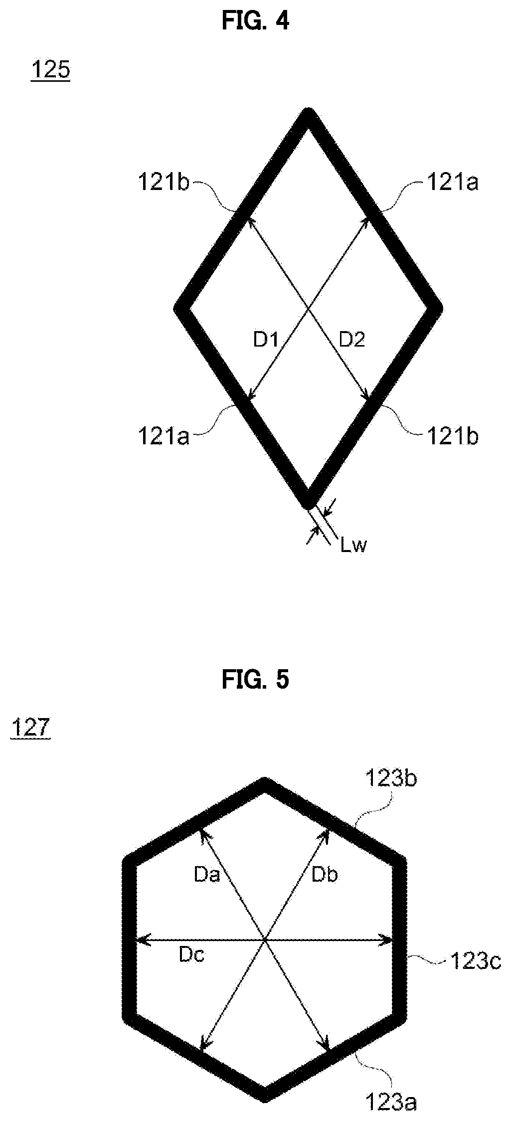
e Visibility Depending on a Minimum Distance Between Opposite Sides of a Unit Cell

Examples and Comparative Examples

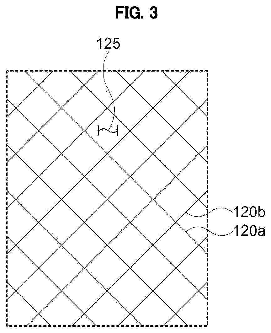
[0101]A mesh structure illustrated in FIG. 3 was formed on the dielectric layer using an alloy (APC) of silver (Ag), palladium (Pd), and copper (Cu). An electrode line was formed to have a line width of 3 μm and an electrode thickness (or a height) was 2000 Å. The minimum distance (indicated as “A” in Table 1) between opposite sides was adjusted by changing a diagonal length in an X-axis direction (indicated as “X” in Table 1) and a diagonal length in a Y-axis direction (indicated as “Y” in Table 1) to prepare film antenna samples of Examples and Comparative Examples. Transmittances and electrode visibilities of the samples were evaluated as described below.

[0102](1) Measurement of Transmittance

[0103]Transmittances of the samples prepared by Examples and Comparative Examples were measured using a spectrophotometer (CM-3600A, Konica Minolta) at a wavelength of 550 nm.

[01...

experimental example 2

ce and Signal Loss Depending on a Line Width of an Electrode Line


PUM

PropertyMeasurementUnit
widthaaaaaaaaaa
widthaaaaaaaaaa
distanceaaaaaaaaaa

Abstract

An antenna device according to an embodiment of the present invention includes a dielectric layer, and an antenna pattern disposed on the dielectric layer. The antenna pattern includes a mesh structure in which unit cells defined by a plurality of electrode lines are assembled. A minimum distance between opposite sides facing each other in the unit cell is from 20 μm to 225 μm, and a line width of the electrode line is from 0.5 μm to 5 μm. A visual recognition of electrodes may be suppressed and a signal sensitivity may be enhanced by using the unit cell structure.

Description

CROSS REFERENCE TO RELATED APPLICATIONS AND CLAIM OF PRIORITY[0001]The present application is a continuation application to International Application No. PCT / KR2019 / 002517 with an International Filing Date of Mar. 5, 2019, which claims the benefit of Korean Patent Application No. 10-2018-0026379 filed on Mar. 6, 2018 at the Korean Intellectual Property Office, the disclosures of which are incorporated by reference herein in their entirety.BACKGROUND1. Field[0002]The present invention relates to an antenna device and a display device including the same. More particularly, the present invention relates to an antenna device including an electrode pattern and a display device including the same.2. Description of the Related Art[0003]As information technologies have been developed, a wireless communication technology such as Wi-Fi, Bluetooth, etc., is combined with a display device in, e.g., a smartphone form. In this case, an antenna may be combined with the display device to provide a ...

Claims


Application Information

Patent Timeline
Patent Type & Authority Patents(United States)
IPC IPC(8): H01Q1/38H01Q1/24H01Q1/42H01Q1/46
CPCH01Q1/38H01Q1/243H01Q1/42H01Q1/46H01Q9/0407H01Q1/40H01Q1/364H01Q1/422
Inventor RYU, HAN SUBOH, YUN SEOKHUH, YOON HOHONG, WON BIN
Owner DONGWOO FINE CHEM CO LTD
Why Eureka
Try Eureka