Antenna device and display device including the same

a display device and antenna technology, applied in the direction of resonant antennas, instruments, identification means, etc., can solve the problems of reducing the detection range of the antenna, so as to reduce the transmittance, increase the electrode recognition, and increase the electrode area

Pending Publication Date: 2022-01-27
DONGWOO FINE CHEM CO LTD
View PDF0 Cites 2 Cited by
  • Summary
  • Abstract
  • Description
  • Claims
  • Application Information

AI Technical Summary

Benefits of technology

The present invention provides an antenna device with improved visual properties and signaling efficiency. Additionally, it prevents a reduction in transmittance and an increase in electrode recognition due to an overlap of electrode lines and an increase of electrode area caused by mis-alignment. The antenna device may be inserted or mounted on a front portion of a display device to improve signaling sensitivity and transmittance and to minimize degradation of an image quality of the display device. The antenna device includes a mesh structure formed of a metallic material to have improved flexibility, and thus may be effectively applied to a flexible display device.

Problems solved by technology

In this case, a space or an area for an antenna may be also limited, and thus a radiator included in the antenna for a signal transfer / reception may overlap a display region of the display device.
Additionally, when the electrodes included in the antenna include a plurality of electrode lines, electrode recognition may be caused to the user due to an overlap or a misalignment of the electrode lines.
For example, Korean Patent Application Publication No. 2013-0095451 discloses an antenna integrated in a display, but fails to consider an image degradation by the antenna in a display device.

Method used


Image

  • Antenna device and display device including the same
  • Antenna device and display device including the same
  • Antenna device and display device including the same

Examples


example 1

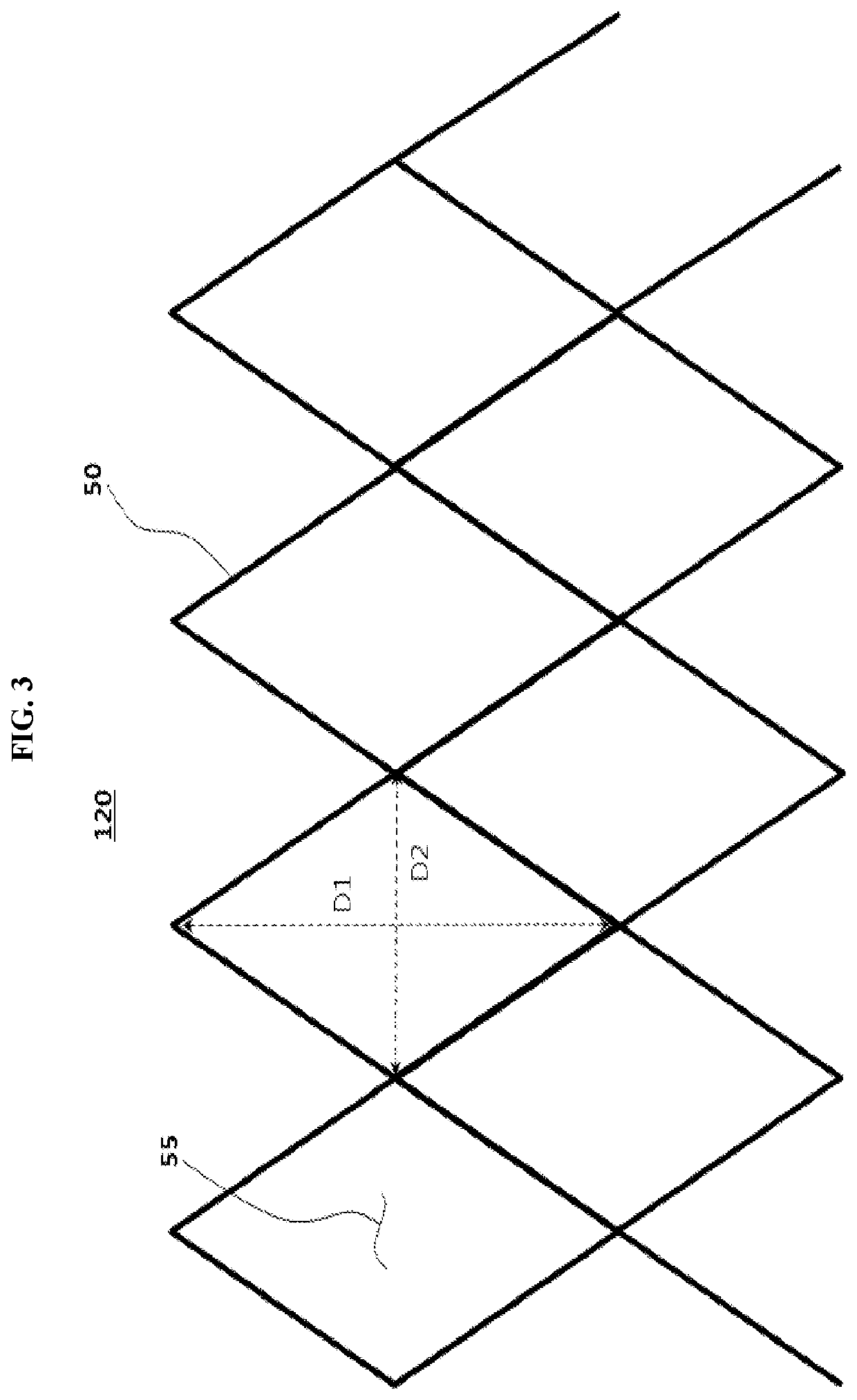
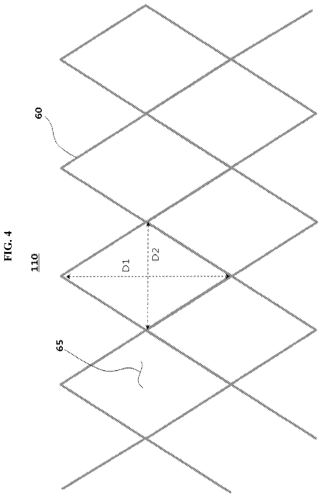
[0100]A first electrode layer and a second electrode layer having a mesh structure on an upper surface and a lower surface of a glass dielectric layer (0.7 T) using an alloy (APC) of silver (Ag), palladium (Pd) and copper (Cu). An electrode line width was 3 μm and an electrode thickness (or a height) was 2000 Å in the mesh structure. A length of an X-direction diagonal line (a short diagonal line) was 200 μm and a length of a Y-direction diagonal line (a long diagonal line) was 400 μm in a rhombus unit cell included in the first and second electrode layers. As illustrated in FIG. 5, the first electrode layer and the second electrode layer was aligned such that each unit cell was divided into four uniform sub-cells.

example 2

[0101]An antenna device was prepared by the same method as that of Example 1 except that a length of an X-direction diagonal line (a short diagonal line) was 300 μm and a length of a Y-direction diagonal line (a long diagonal line) was 600 μm in a rhombus unit cell included in the first and second electrode layers.

experimental example

[0103](1) Evaluation of Antenna Driving Properties

[0104]A feeding was performed to the antenna devices of Examples and Comparative Example so that the first electrode layer served as a radiator and the second electrode layer served as a ground electrode. Parameters relating to antenna properties (S11, Re(Z), Im(Z), Gain, Directivity, Radiation efficiency) were measured using Vector Network Analyzer (MS4644B manufactured by Anritsu) and a radiation chamber. The results are shown in Table 1 below (※ Radiation efficiency (%)=(Gain / Directivity)*100).

TABLE 1RadiationResonanceDirec-Effi-FrequencyS11ReImGaintivityciency(GHz)(dB)(Z)(Z)(dBi)(dBi)(%)Example 26.97−7.4 25.4022.895.797.6475.781Example 26.65−6.3521.7922.725.767.3378.582Comparative26.97−6.4324.9428.985.617.5374.51Example

[0105]Referring to Table 1, when the mesh structures were staggered as in Examples, the antenna properties were substantially maintained without excessive change or degradation.

[0106](2) Evaluation of Transmittance...


PUM


Abstract

An antenna device according to an embodiment of the present disclosure includes a dielectric layer, a first electrode layer disposed on an upper surface of the dielectric layer, the first electrode layer including a radiator and having a first mesh structure, and a second electrode layer disposed on a lower surface of the dielectric layer, the second electrode layer having a second mesh structure. The first mesh structure and the second mesh structure are aligned to be offset or staggered from each other with respect to the dielectric layer in a planar view.

Description

CROSS REFERENCE TO RELATED APPLICATIONS AND CLAIM OF PRIORITY[0001]The present application is a continuation application to International Application No. PCT / KR2020 / 004400 with an International Filing Date of Mar. 31, 2020, which claims the benefit of Korean Patent Applications No. 10-2019-0038332 filed on Apr. 2, 2019 at the Korean Intellectual Property Office, the disclosures of which are incorporated by reference herein in their entirety.BACKGROUND1. Field[0002]The present invention relates to an antenna device and a display device including the same. More particularly, the present invention related to an antenna device including electrode patterns and a display device including the same.2. Description of the Related Art[0003]As information technologies have been developed, a wireless communication technology such as Wi-Fi, Bluetooth, etc., is combined with a display device in, e.g., a smartphone form. In this case, an antenna may be combined with the display device to provide a ...

Claims


Application Information

Patent Timeline
IPC IPC(8): H01Q1/36H01Q1/48
CPCH01Q1/36H01Q1/243H01Q1/48H01Q1/38H01Q1/50H01Q1/24G09F9/00H01Q1/364H01Q9/0407H01Q1/22
Inventor RYU, HAN SUBPARK, DONG PILOH, YUN SEOK
Owner DONGWOO FINE CHEM CO LTD
Why Eureka
Try Eureka