Mosquito trapping device

a mosquito and device technology, applied in the field of insect trapping, can solve the problems of undermining the overall mosquito trapping ability, the trapping method has limitations, etc., and achieves the effects of increasing the amount of wind blowing, wide application range, and increasing the efficiency of mosquito killing

Active Publication Date: 2022-05-17
FOSHAN GREENYELLOW ELECTRIC TECH
View PDF23 Cites 0 Cited by
  • Summary
  • Abstract
  • Description
  • Claims
  • Application Information

AI Technical Summary

Benefits of technology

[0005]The objective of the present invention is to provide a mosquito trapping device that has good mosquito attracting abilities, a simple structure, and is easy to use.
[0025]3. The carbon dioxide generating module is provided with a one-way valve and a solenoid valve, which can automatically control the working time, the carbon dioxide emission, and the change of carbon dioxide emission of the mosquito trapping device. This allows the device to meet operational requirements in different regions, different seasons, and different applications, providing flexibility and a wide application range.
[0027]The present invention provides a mosquito-killing module, which comprises a fan, a wind director, and a mosquito storage box. The fan is provided with blades that are separated from each other by a gap and have a certain angle of inclination. Furthermore, a plurality of through-holes is provided in the wheel hub. These features increase the amount of wind blowing in the axial direction in the mosquito-killing module, which ensures that the mosquitoes can be quickly air-dried and dehydrated to death. Alternatively, the mosquitoes may suffer from dizziness that leads to death during their transfer. This prevents the escape of the mosquitoes, increasing the efficiency of mosquito killing.

Problems solved by technology

However, the aforementioned light-trapping method has its limitations: it is limited by space and obstacles; any portion of the mosquito trap blocked by obstacles would not be able to attract mosquitoes, undermining the overall mosquito trapping ability.

Method used


Image

  • Mosquito trapping device
  • Mosquito trapping device
  • Mosquito trapping device

Examples


Embodiment Construction

[0035]To more clearly illustrate the aims, technical solutions, and beneficial effects of the present invention, the present invention is further described in detail below. It should be noted that the expressions “upper”, “lower”, “left”, “right”, “front”, “back”, “inside”, and “outside” herein are only based on the accompanying drawings of the present invention and are not intended to limit the scope of the present invention.

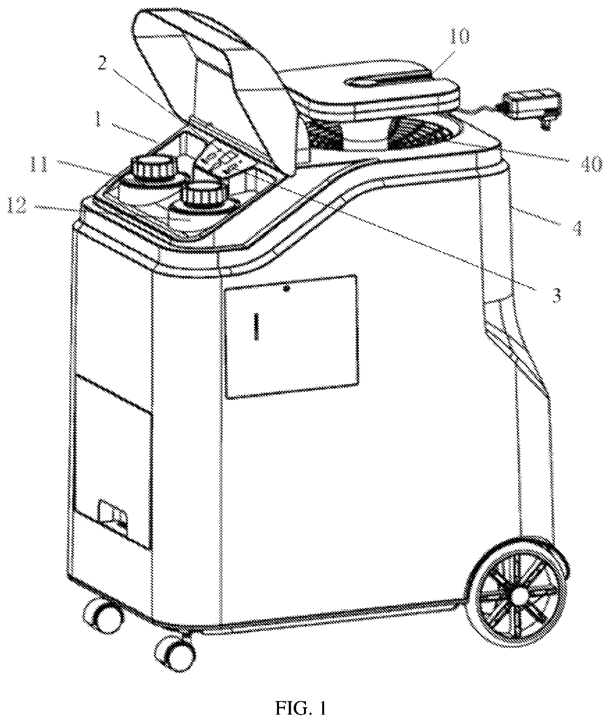
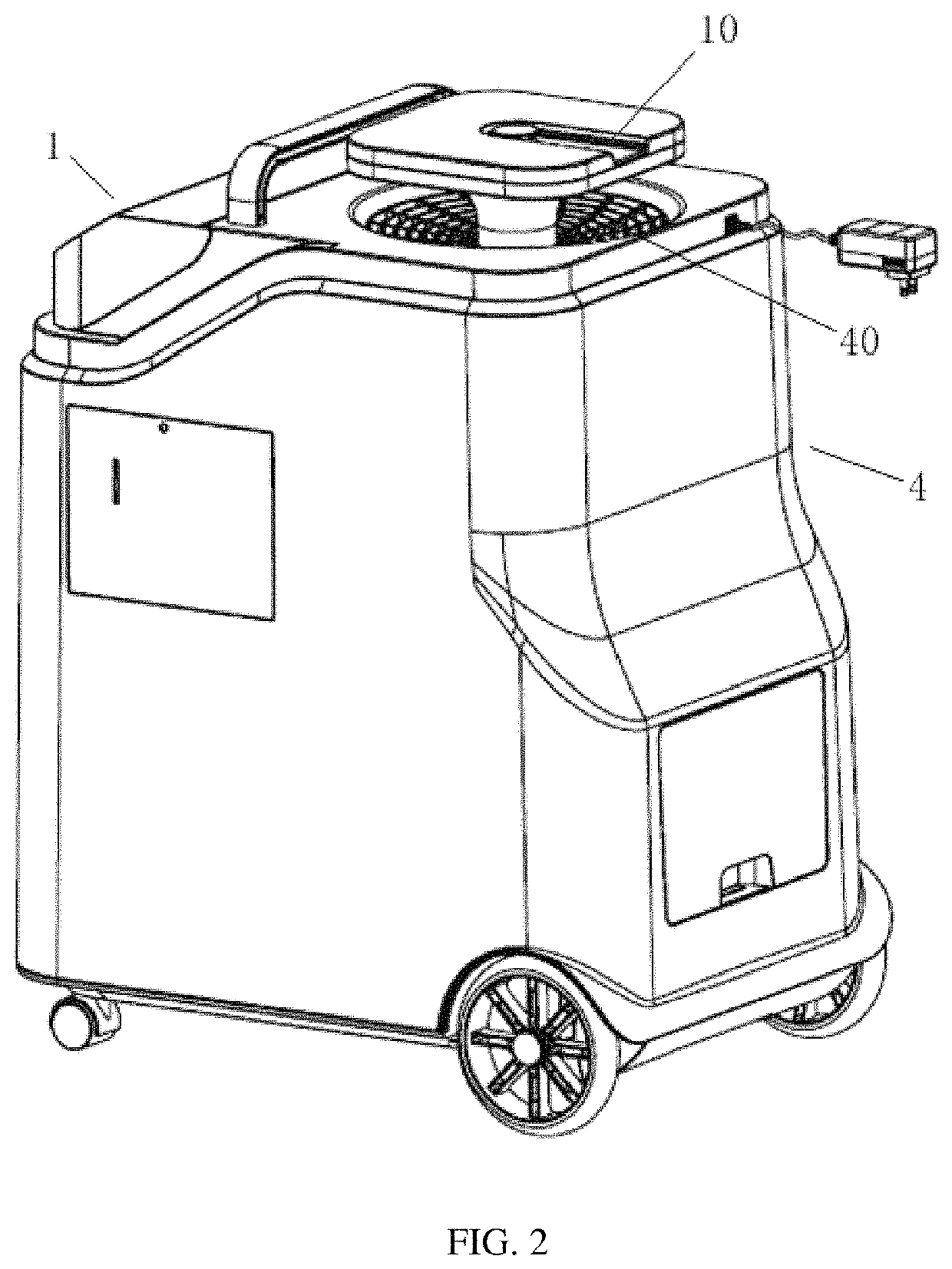
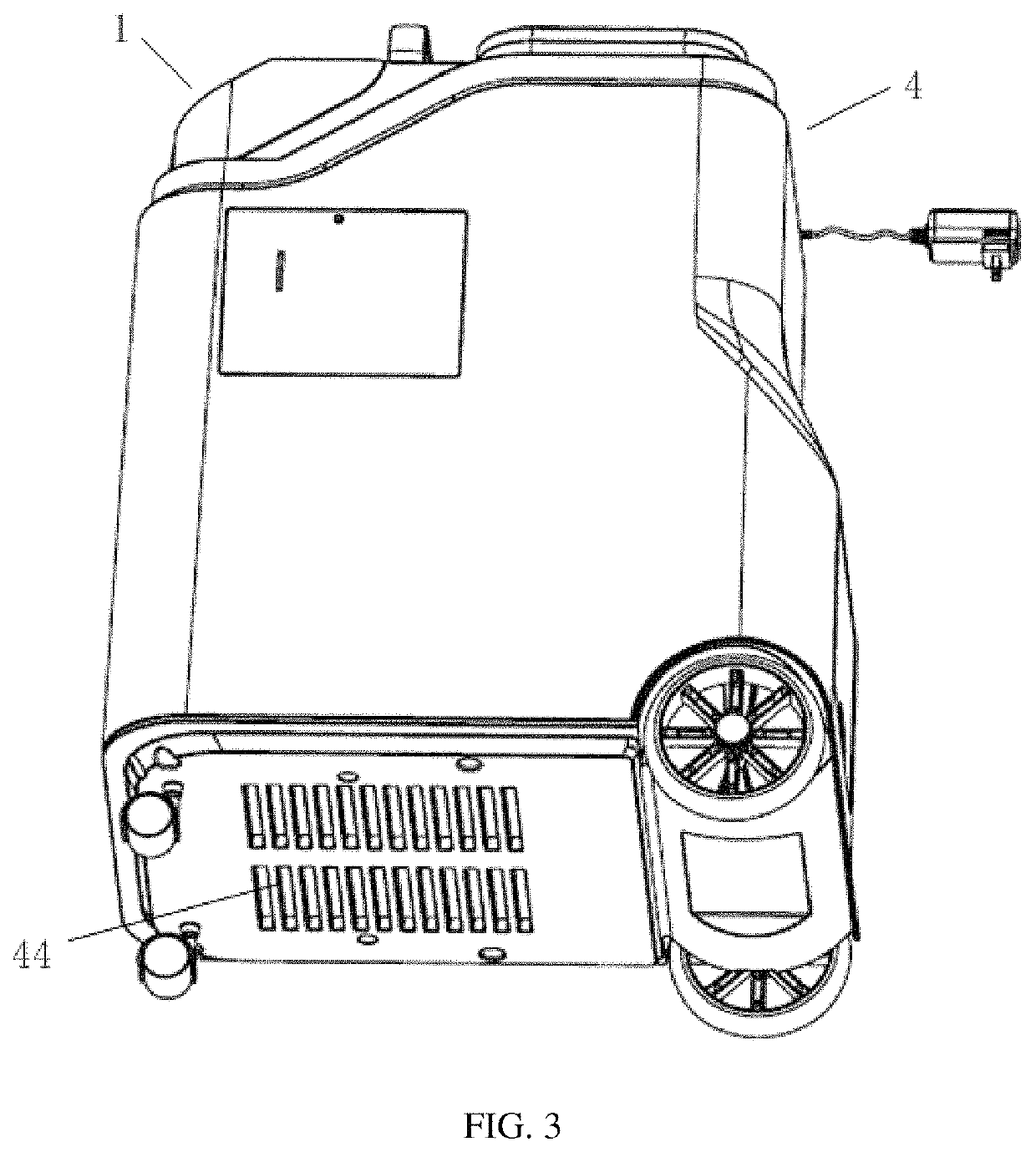
[0036]Referring to FIGS. 1 to 4, the present embodiment discloses a mosquito trapping device, wherein a carbon dioxide generating module 1, a temperature control module 2, a humidity control module 3, and a mosquito-killing module 4 are provided in its casing. The carbon dioxide generating module 1, the temperature control module 2, and the humidity control module 3 attract the mosquitoes, then the mosquitoes are lured into the mosquito trapping device via the mosquito-killing module 4. Inside the mosquito-killing module 4, the mosquitoes are air-dried and dehy...


PUM


Abstract

The present invention provides a mosquito trapping device, which comprises a carbon dioxide generating module, a temperature control module, a humidity control module, and a mosquito-killing module. The carbon dioxide generating module comprises a container A and a container B, a solution in the container A reacts with a solution in the container B to generate carbon dioxide; the temperature control module controls a temperature of the mosquito trapping device to be between 38° C. and 45° C.; the humidity control module controls humidity of the mosquito trapping device to be between 50% and 80%; the mosquito-killing module generates a guiding wind having a wind speed of 0.7 m / s to 15 m / s. The present invention has a good mosquito-attracting effect and a desirable mosquito-killing ability.

Description

CROSS REFERENCE TO RELATED APPLICATIONS[0001]The present application claims the benefit of Chinese Patent Application No. 201910757895.6 filed on Aug. 16, 2019, the contents of which are incorporated herein by reference in their entirety.FIELD OF THE INVENTION[0002]The invention relates to the field of insect trapping, in particular to a mosquito trapping device.BACKGROUND OF THE INVENTION[0003]According to statistics, there are more than 2,000 kinds of mosquitoes on earth, among them more than 200 kinds reside in China. There are three main genera of mosquitoes that may harm humans: Anopheles, Culex, and Aedes. Existing mosquito traps generally employ UV lamps to generate specific wavelengths of light to attract and kill mosquitoes. However, the aforementioned light-trapping method has its limitations: it is limited by space and obstacles; any portion of the mosquito trap blocked by obstacles would not be able to attract mosquitoes, undermining the overall mosquito trapping ability...

Claims


Application Information

Patent Timeline
Patent Type & Authority Patents(United States)
IPC IPC(8): A01M1/02A01M1/10A01M1/06A01M1/20
CPCA01M1/023A01M1/06A01M1/106A01M1/2094A01M2200/012C01B32/50Y02A50/30
Inventor QIN, XINZONGWANG, RUOFEIHU, KEKE
Owner FOSHAN GREENYELLOW ELECTRIC TECH
Why Eureka
Try Eureka