Composite thermal interface objects

a technology of thermal interface objects and objects, applied in the field of thermal interface objects, can solve the problems of cpu failure, cpu failure, and cpu failure, and achieve the effects of reducing or preventing damage to electrical components, reducing adherence to electrical components, and high thermal conductivity

Active Publication Date: 2022-05-17
INT BUSINESS MASCH CORP
View PDF24 Cites 0 Cited by
  • Summary
  • Abstract
  • Description
  • Claims
  • Application Information

AI Technical Summary

Benefits of technology

[0006]One advantage of the present disclosure is the ability to make a composite thermal interface object. The composite thermal interface object may provide high thermal conductivity while reducing or preventing damage to electrical components upon removal. By adding a stiffer layer of thermal interface material to a complaint thermal interface object, adherence to the electrical components may be reduced (which may reduce or prevent damage to the electrical components), while retaining the high thermal conductivity of compliant thermal interface pads. Additionally, by forming a surface of the composite thermal interface object based on a surface of a component of a thermal interface, the composite thermal interface object may reduce air gaps and further increase thermal conductivity.

Problems solved by technology

However, a conformable TIM may become stuck to the electrical component (e.g., a lid of a central processing unit (CPU)), to the heat sink, or both.
However, the adherence of the conformal TIM may not be strong enough to support the CPU, and the CPU may subsequently fall back down and damage the socket.

Method used


Image

  • Composite thermal interface objects
  • Composite thermal interface objects
  • Composite thermal interface objects

Examples


Embodiment Construction

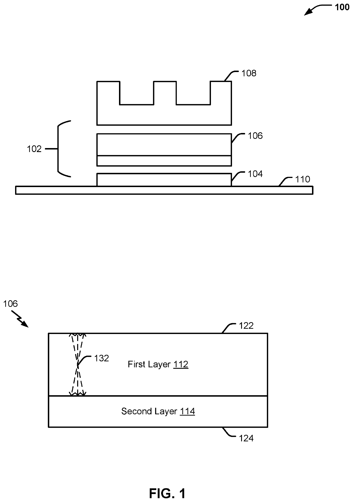
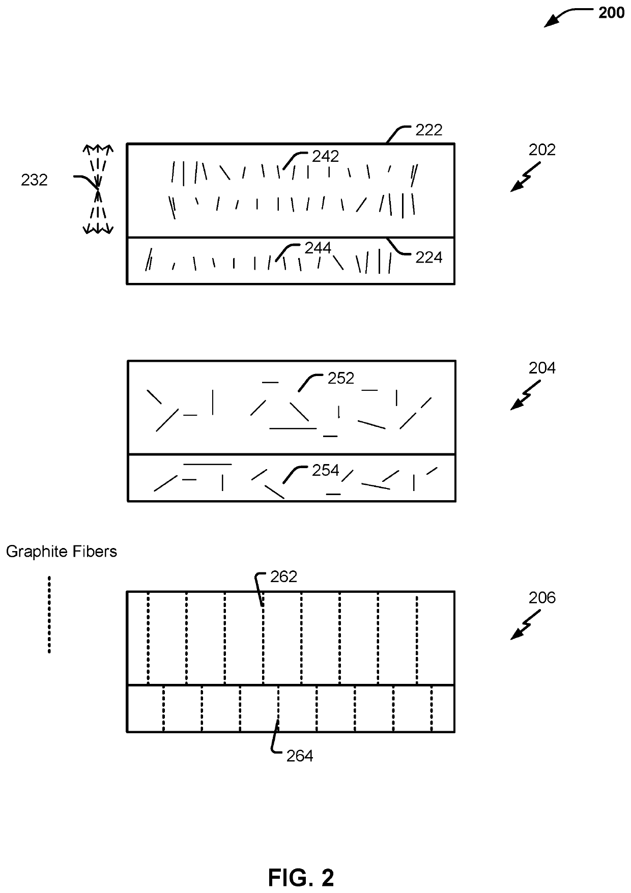
[0014]The present disclosure relates to composite thermal interface objects suitable for use in thermal interfaces and methods for forming a composite thermal interface object. Composite thermal interface objects may include multiple layers of different thermal interface materials (TIMs). A TIM is a material that has relatively high thermal conductivity as compared to other materials or mediums (e.g., air). A TIM or a composite thermal interface object may be inserted between a heat producing device (e.g. a heat source) and a heat dissipation device (e.g. a heat sink) to form a thermal interface.

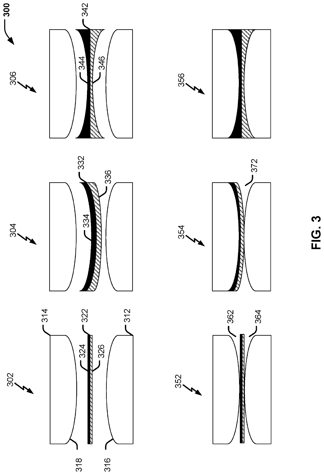
[0015]The heat source and heat sink surfaces may each have a combination of surface roughness and surface non-flatness. On a macroscopic level, this roughness is non-planar, (e.g., a concave surface, a convex surface, a wavy surface, an irregular surface, or a combination thereof) across the surface. When the heat source and the heat sink are joined to form a thermal interface, the surface r...


PUM

PropertyMeasurementUnit
thicknessaaaaaaaaaa
thicknessaaaaaaaaaa
thicknessaaaaaaaaaa

Abstract

In an example, a composite thermal interface object includes a first layer including a first thermal interface material that has first compliance characteristics. The first layer includes first graphite fibers, and the first graphite fibers are aligned in a direction that is substantially orthogonal to a surface of the first layer. The composite thermal interface object further includes a second layer including a second thermal interface material that has second compliance characteristics that are different from the first compliance characteristics.

Description

I. FIELD OF THE DISCLOSURE[0001]The present disclosure relates generally to thermal interface objects.II. BACKGROUND[0002]Thermal interface materials (TIMs) are materials that are employed to reduce thermal resistance at a thermal interface of a heat source and a heat exchanger (e.g., a heat sink). Conformable TIMs (e.g., a conformal thermal interface pad) are TIMs that are able to conform, under an applied force (e.g., pressure), to a surface. Because conformable TIMs reduce the presence of air gaps between surfaces of the heat source (e.g., an electrical or electronic component) and the heat sink, they can improve thermal conductivity. However, a conformable TIM may become stuck to the electrical component (e.g., a lid of a central processing unit (CPU)), to the heat sink, or both. During removal of the heat sink, the conformal TIM may adhere to the heat sink and the lid of the CPU and may lift the CPU out of its socket (e.g., a land grid array (LGA)). However, the adherence of th...

Claims


Application Information

Patent Timeline
Patent Type & Authority Patents(United States)
IPC IPC(8): H01L23/373B29L31/18B29C43/18H01L23/42B29K507/04B29K105/18B29K105/16B29C43/20
CPCH01L23/3733B29C43/18H01L23/42B29C43/203B29C2043/189B29K2105/16B29K2105/18B29K2507/04B29K2995/0013B29L2031/18
Inventor CZAPLEWSKI, SARAH K.KUCZYNSKI, JOSEPHMILLER, MELISSA K.MORONES, REBECCA NADEAU
Owner INT BUSINESS MASCH CORP
Why Eureka
Try Eureka