

Stretchable device system and electronic device
a technology of a strangler and a device body, applied in the field of strangler and an electronic device, can solve the problem of permanent damage of the device, and achieve the effect of reducing or preventing the damage of the devi
- Summary
- Abstract
- Description
- Claims
- Application Information
AI Technical Summary
Benefits of technology
Problems solved by technology
Method used
Image

Examples
examples 1 to 3
[0119]Strain-stress responses according to the geometrically stretchable structures are evaluated.
[0120]The strain-stress responses are evaluated from a mechanical simulation using a COMSOL Multiphysics software with assuming a structure that a stretch controlling layer (the geometrically stretchable structures shown in FIGS. 4A to 4C) is inserted into a stretchable layer (200 μm×200 μm).
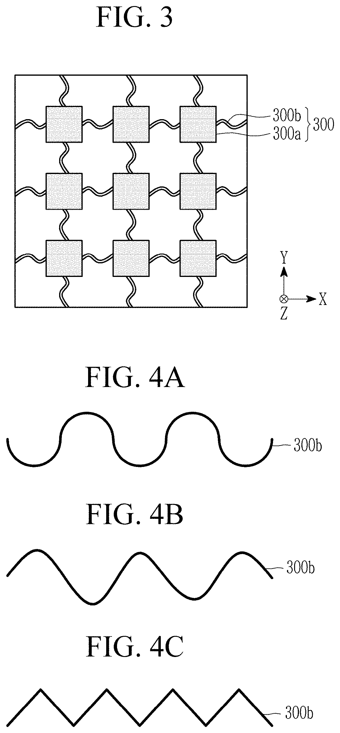
[0121]It is set as follows.[0122]Elastic modulus (Young's Modulus) of stretchable layer: 13×106 Pa[0123]Elastic modulus (Young's Modulus) of stretch controlling layer: 2.5×10⁹ Pa[0124]Poisson ratio: 0.35,[0125]Density: 1200 kg / m3,[0126]Thickness: 1 μm,[0127]Shape: FIG. 4A (half circle) (Example 1), FIG. 4B (sinusoidal) (Example 2), and FIG. 4C (rectangular) (Example 3).
[0128]The results are shown in FIG. 13 and Table 1.
[0129]FIG. 13 is a strain-stress graph of the geometrically stretchable structures according to Examples 1 to 3.
TABLE 1Geometric maximumLength:thickness ratiostrain (%)(@critical stra...
examples 4 to 7
[0132]Strain-stress responses of the geometrically stretchable structures depending on an elastic modulus are evaluated.
[0133]The strain-stress responses of the geometrically stretchable structures depending on an elastic modulus are evaluated from a mechanical simulation using a COMSOL Multiphysics software with assuming a structure that a stretch controlling layer (a geometrically stretchable structure shown in FIG. 4C) is inserted into a stretchable layer (200 μm×200 μm).
[0134]It is set as follows.[0135]Elastic modulus (Young's Modulus) of stretchable layer: 13×106 Pa[0136]Elastic modulus (Young's Modulus) of stretch controlling layer (geometrically stretchable structure): 0.1×10⁹ Pa (Example 4), 1×10⁹ Pa (Example 5), 2.5×10⁹ Pa (Example 6), 1.0×10¹⁰ Pa (Example 7)[0137]Poisson ratio: 0.35,[0138]Density: 1200 kg / m3 [0139]Thickness: 1 μm[0140]Length: sphere[0141]Shape: FIG. 4C
[0142]The results are shown in FIG. 14.
[0143]FIG. 14 is a strain-stress graph according to the elastic mod...
example 8
[0145]On a glass substrate coated with a sacrificial layer, a 4.5 μm-thick lower stretchable layer (a stretching ratio: 700%, an elastic modulus: −1 MPa) is formed by coating a solution in which styrene-ethylene-butylene-styrene (SEBS) including a styrene structural unit and an ethylene / butylene structural unit in a ratio of 20:80 (w / w) (H1052, Asahi Kasei) and a hardener in toluene and then, drying, curing, and patterning it. Subsequently, on the lower stretchable layer, a polyimide precursor solution is coated and treated through photolithography to form a stretch controlling layer including a 10 μm-thick serpentine-shaped polyimide pattern (an elastic modulus: about 2.5 GPa). On the stretch controlling layer, a solution prepared by dissolving styrene-ethylene-butylene-styrene (SEBS) (H1052, Asahi Kasei) and a hardener in toluene is coated, dried, cured, and patterned to form a 10 μm-thick stretchable layer (a stretching ratio: about 20%, an elastic modulus: about 80 MPa), manufac...
PUM
| Property | Measurement | Unit |
|---|---|---|
| elastic modulus | aaaaa | aaaaa |
| elastic modulus | aaaaa | aaaaa |
| elastic modulus | aaaaa | aaaaa |
Abstract
Description
Claims
Application Information