Test specimen for validating operating parameters of a method for the additive manufacturing of a part by laser melting on powder beds

a technology of laser melting and test specimens, which is applied in the field of test specimens for validating the operating parameters of the additive manufacturing method of a part by laser melting on the powder bed, can solve the problems of long and costly experimentation, time required for the manufacture and metallographic analysis of each geometry and for each parameter, and long step and laborious, so as to reduce the industrial research process and achieve quick overview

Active Publication Date: 2022-05-31
SAFRAN HELICOPTER ENGINES
View PDF5 Cites 0 Cited by
  • Summary
  • Abstract
  • Description
  • Claims
  • Application Information

AI Technical Summary

Benefits of technology

[0011]The step of identifying manufacturing parameters to obtain a dense and compliant material health is essential. It is therefore advantageous to develop solutions that reduce the industrial process of researching these parameters. For this purpose, we propose a new test specimen geometry that allows observing material health, as well as surface conditions and the manufacturability of certain particular shapes. The test specimen, which can be small in size, allows multiplying on the same production tray the number of sets of operating parameters evaluated and thus to have a very quick overview of the quality of the parameters tested in terms of material health, manufacturability, mass yield, etc.

Problems solved by technology

In this case, a complete new iteration is necessary and this iteration is long and costly.
This evaluation is done by image analysis on a micrographic section, which makes this step tedious.
The disadvantage of this technique is the time required for the manufacture and metallographic analysis of each geometry and for each parameter.
The plurality of tests generates a lot of time spent between successive iterations.
However, in an industrial context of manufacturing of parts, the time spent on the development of construction parameters in laser melting limits the reactivity of this method for manufacturing.

Method used


Image

  • Test specimen for validating operating parameters of a method for the additive manufacturing of a part by laser melting on powder beds
  • Test specimen for validating operating parameters of a method for the additive manufacturing of a part by laser melting on powder beds

Examples


Embodiment Construction

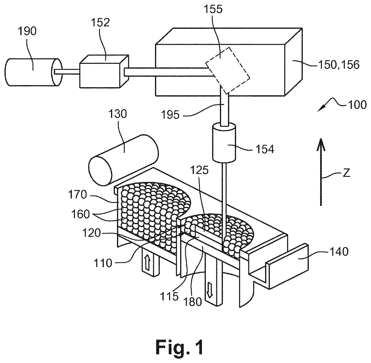
[0030]FIG. 1 shows a machine for manufacturing a part by additive manufacturing and in particular by selective melting of powder layers by high energy beam.

[0031]The machine includes a feed tray 170 containing metal powder, a roller 130 to transfer this powder from this tray 170 and spread a first layer 110 of this powder on a construction support 180 (it can be a solid support, a portion of another part or a support grid used to facilitate the construction of certain parts).

[0032]The machine also includes a recycling bin 140 to recover a small part of the used powder (especially not melted or sintered) and most of the excess powder, after spreading the powder layer on the construction support 180. Thus, most of the powder in the recycling bin is new powder. Also, this recycling bin 140 is commonly referred to by the profession as an overflow bin or ashtray.

[0033]This machine also includes a laser beam 195 generator 190, and a control system 150 capable of directing this beam 195 to...


PUM

PropertyMeasurementUnit
angleaaaaaaaaaa
angleaaaaaaaaaa
angleaaaaaaaaaa

Abstract

A test specimen for validating operating parameters of a method for the additive manufacturing of a part by laser melting on powder beds includes at least one upper face, at least one lower face and side faces, including a front side face and a rear side face that are substantially on opposite sides from one another. The test specimen has at least one recess opening onto the front and rear side faces, the recess having a substantially triangular cross sectional shape being delimited by three internal faces, including a first lower internal face oriented upwards, a second upper internal face oriented downwards, and a third upper internal face which defines a narrow wall with one other of the side faces, which is inclined.

Description

TECHNICAL FIELD[0001]This invention concerns a test specimen for validating operating parameters of an additive manufacturing method of a part by laser melting on powder beds.BACKGROUND[0002]The prior art includes patent applications published under the numbers FR-A1-3 029 829, US-A1-2013 / 112366, US-A1-2010 / 174392, US-A1-2014 / 300017 and US-A1-2015 / 219572.[0003]The additive manufacturing, particularly by laser melting on powder beds, is an increasingly used method with many advantages. Before producing a part by additive manufacturing, it is necessary to define operating parameters, such as laser beam power, beam scanning speed, etc., that are specific to the material used. In the case of parts for the aeronautical industry, the material is generally a metal alloy and the additive manufacturing method is of the SLM type (Selective Laser Melting).[0004]The operating parameters are defined in two steps. A first step consists in searching for parameters that allow to obtain a healthy ma...

Claims


Application Information

Patent Timeline
Patent Type & Authority Patents(United States)
IPC IPC(8): B29L31/40G07C3/14B29C64/153B33Y80/00
CPCG07C3/143B29C64/153B29L2031/40B33Y80/00B33Y10/00B33Y50/02B29C64/393G01N1/2806Y02P10/25B22F2999/00B22F5/10B22F12/49B22F10/385B22F12/67B22F12/44B22F10/28B22F10/73B22F10/31B22F12/53B22F2203/03
Inventor DANIS, YANNMARCHAND, ALEXISGERMAIN, AURÈLE
Owner SAFRAN HELICOPTER ENGINES
Why Eureka
Try Eureka