Roller configured to support a rotary milking platform

a technology of a rolling machine and a supporting plate, which is applied in the direction of rotary machine parts, mechanical equipment, agriculture tools and machines, etc., can solve the problems of stress in the rolling machine and the inability of the flat running surface to provide a load on the area, and achieve the effect of improving the life tim

Active Publication Date: 2022-06-14
DELAVAL HLDG AB
View PDF10 Cites 0 Cited by
  • Summary
  • Abstract
  • Description
  • Claims
  • Application Information

AI Technical Summary

Benefits of technology

[0005]The object of the present invention is to provide a roller configured to support a rotary milking platform which has a design such that an improved life time is provided.
[0007]Since the flat running surfaces are out of contact with the bottom surface defining the circumferential recess, the flat running surfaces are not able to provide a load on the area of the roller provided with the circumferential recess. As a result, the stress concentration in this usually stress exposed area will be low which substantially eliminates the risk for deformations and crack formations. Furthermore, such a circumferential recess prevents that possible sharp edge portions of the flat running surfaces, damages the roller in this area. Thus, the present roller will obtain less stress concentrations and substantially no damages in said usually stress exposed area which results in a longer life time of the present roller in relation to a conventional roller.
[0010]According to an embodiment of the invention, the inner surface of the flange forms an angle in relation to a plane perpendicular to the rotation axis of the roller. A contact portion of the rail members is usually designed with a rectangular cross section with side surfaces arranged on opposite sides of the flat running surface. At an angular deviation between a roller and a flat running surface of a rail member, there is a great risk that said side surfaces of the rail members comes in contact with the inner surface of the flange. Such a contact may results in damages of the flange. In any event, it will increase the rolling friction of the roller. The above mentioned design of the inner surface of the flange makes it is possible to avoid that a side surface to the flat rolling surface come in contact with the inner surface of the flange at relevant angle deviations between the flat running surfaces of the rail members and the roller.
[0013]According to a further embodiment of the invention, the roller is manufactured of a material body in one piece. The roller may be a homogeneous body of a wear resistant material. Such a material may be a nylon material. Rollers made of a nylon have excellent impact resistance, good load capacity, good chemical resistance, low coefficient of friction, good vibration absorbing properties and they can be manufactured at a low cost.

Problems solved by technology

A roller for a rotary platform is subjected to large loads which results in stresses in the roller.
Since the flat running surfaces are out of contact with the bottom surface defining the circumferential recess, the flat running surfaces are not able to provide a load on the area of the roller provided with the circumferential recess.

Method used


Image

  • Roller configured to support a rotary milking platform
  • Roller configured to support a rotary milking platform
  • Roller configured to support a rotary milking platform

Examples


Embodiment Construction

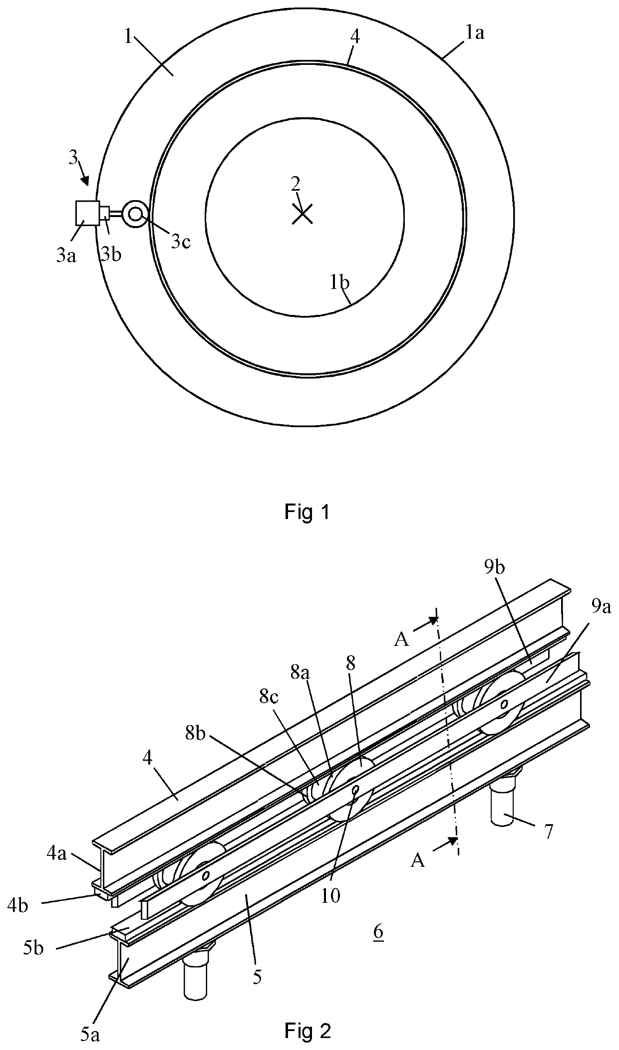
[0021]FIG. 1 shows, from the below, a rotary annular platform 1 for milking of cows. The platform 1 is rotatably arranged around a vertical axis 2. The annular platform 1 has an outer edge portion 1a and an inner edge portion 1b. The platform 1 is driven by a drive unit 3. The drive unit 3 comprises an electric motor 3a, an integrated reduction gear box 3b and a drive wheel 3c mounted in contact with a side surface of an upper circular rail member 4 fixedly attached to the platform 1. The drive wheel 3c may be a pneumatic tyre. Such a drive wheel 3c makes the drive unit shock resistant as the tyre provides a cushioning effect. The drive unit 3 has a smooth start and stop action. The drive unit 3 may be infinitely variable in speed in either a clockwise or counter-clockwise direction. The upper circular rail member 4 is fixedly attached to a lower surface of the platform 1 by, for example, welding.

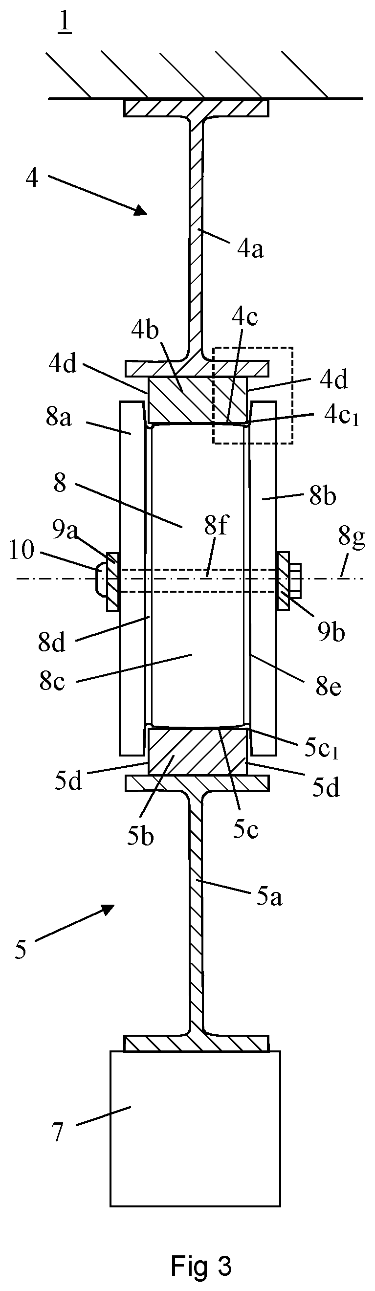
[0022]FIG. 2 shows a part of a support arrangement for the platform 1. The upper rail m...


PUM


Abstract

A roller is provided that is configured to support of a rotary platform. The roller includes at least one side flange including an inner surface, a rolling surface to be in contact with a flat running surface of an upper rail member fixedly connected to the rotary platform and a flat running surface of a lower rail member stationary arranged. The roller includes a circumferential recess connecting the rolling surface to the inner surface of the side flange and that the circumferential recess has a depth such that the flat running surfaces of the upper rail member and the lower rail members are out of contact with a bottom surface of the circumferential recess at a potential angle deviation between the flat running surfaces of the rail members and a rotation axis of the roller.

Description

[0001]This application is the U.S. national phase of International Application No. PCT / SE2019 / 050566 filed Jun. 14, 2019 which designated the U.S. and claims priority to SE Patent Application No. 1850747-5 filed Jun. 19, 2018, the entire contents of each of which are hereby incorporated by reference.THE BACKGROUND OF THE INVENTION AND PRIOR ART[0002]The present invention relates to a roller configured to support a rotary milking platform.[0003]Conventional support arrangements for rotary milking platforms comprises rollers provided with a cylindrical rolling surfaces to be arranged between a flat running surface of an upper rail member connected to the rotary platform and a flat running surface of a stationary arranged lower rail member. The rollers provide a vertical support of the platform. Usually, the rollers comprise flanges. In this case, the rollers also provide a positioning of the platform in a horizontal plane. However, it is difficult to arrange the flat running surface o...

Claims


Application Information

Patent Timeline
Patent Type & Authority Patents(United States)
IPC IPC(8): F16C19/50A01K1/12F16C13/00F16C29/04F16C33/36F16C23/08F16C33/34
CPCF16C19/507A01K1/126F16C13/006F16C23/088F16C29/04F16C33/34F16C33/363F16C2300/14F16C2310/00F16C13/00F16C33/36A01K1/12
Inventor KALEMPA, WALENTY
Owner DELAVAL HLDG AB
Why Eureka
Try Eureka