
Magnetic apparatus for protecting a protected area

Active Publication Date: 2022-07-05
METRASENS
View PDF6 Cites 0 Cited by
  • Summary
  • Abstract
  • Description
  • Claims
  • Application Information

AI Technical Summary

Benefits of technology

The invention relates to a system for detecting and screening for magnetic objects in a protected zone. The system uses a threshold detector to reduce noise and a low pass filter to reduce noise present in the output. The system can detect and track the movement of magnetic objects and differentiate between them and unwanted external influences. The system uses digital processing to record the time evolution of the processed signals and make further deductons about the nature, speed, and track of the targets passing into the protected zone, which may aid in discriminating about potential hazards and issuing warnings. The system can be used to protect a doorway with the protected zone of one apparatus extending across the doorway and the protected zone of the other apparatus extending through to the other side of the doorway.

Problems solved by technology

However, a common false-alert can occur when a non-magnetic person or object enters zone IV, the MRI scanner room, triggering the secondary sensor whilst the magnetic gradiometer is detecting something else such as a control room chair moving.
In the case of a patient screening FMDS, an unrelated magnetic object may be moving at the same time as a patient is being magnetically screened, again giving rise to a false positive alert.
Where there are too many false positive alerts then staff can become ‘alarm fatigued’ and begin to ignore the alerts.
This reduces the effectiveness of these systems.
They may also be used to guard a doorway in a similar manner to the medical application, but, without a low false alert rate and a more uniform sensing performance across the door, the utilization will be limited.

Method used


Image

  • Magnetic apparatus for protecting a protected area
  • Magnetic apparatus for protecting a protected area
  • Magnetic apparatus for protecting a protected area

Examples


Embodiment Construction

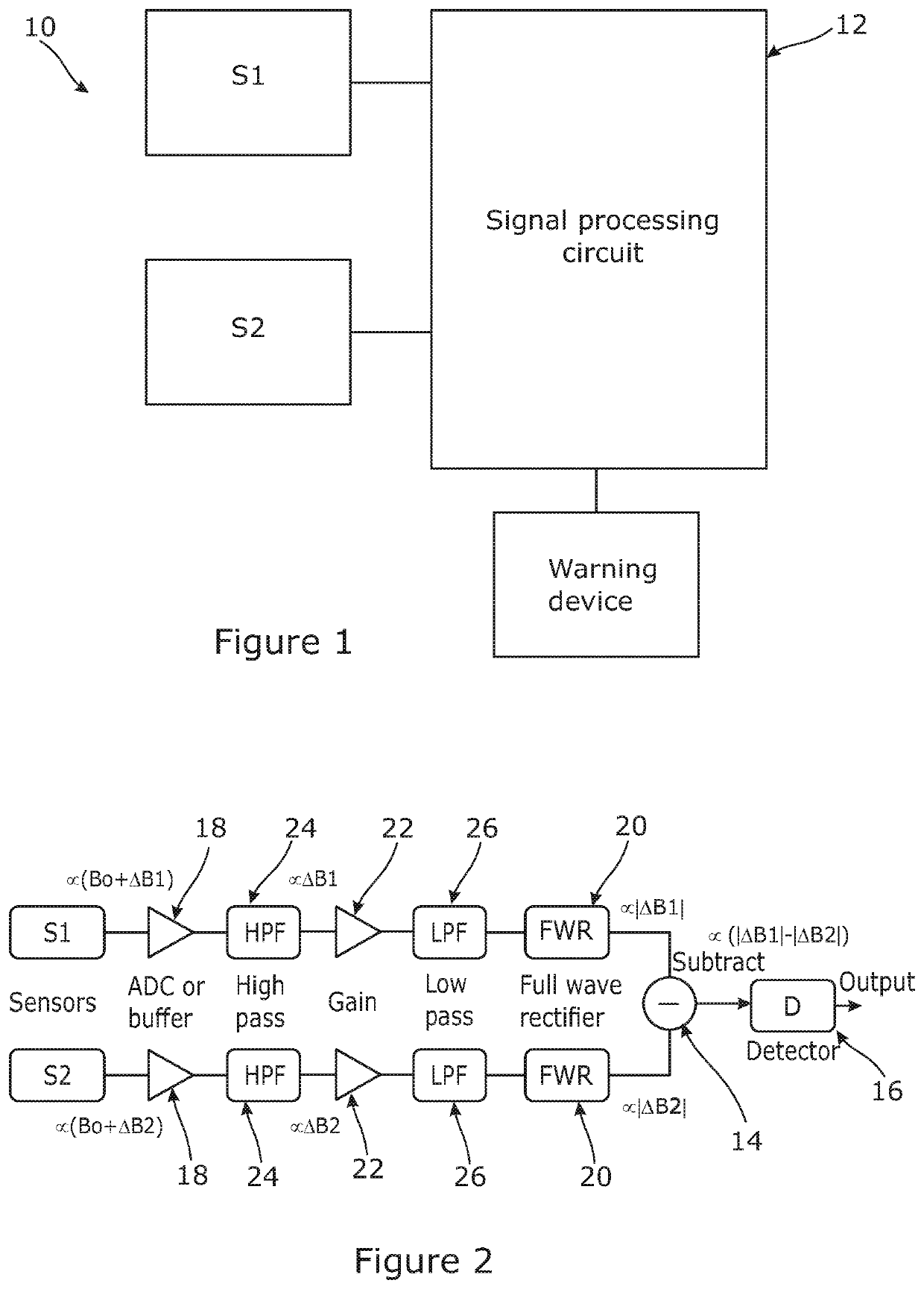
[0082]Referring to FIG. 1, the main function components of an embodiment of an apparatus 10 in accordance with an aspect of the invention is shown.

[0083]The apparatus 10 comprises two vector type magnetic sensors S1, S2. Each one is adapted to measure an ambient magnetic field within a localised volume of space defined by a respective first or second zone of sensitivity of the magnetic sensor S1, S2, and to produce a corresponding measurement signal indicative of the absolute value of the magnetic field in the respective first or second zone.

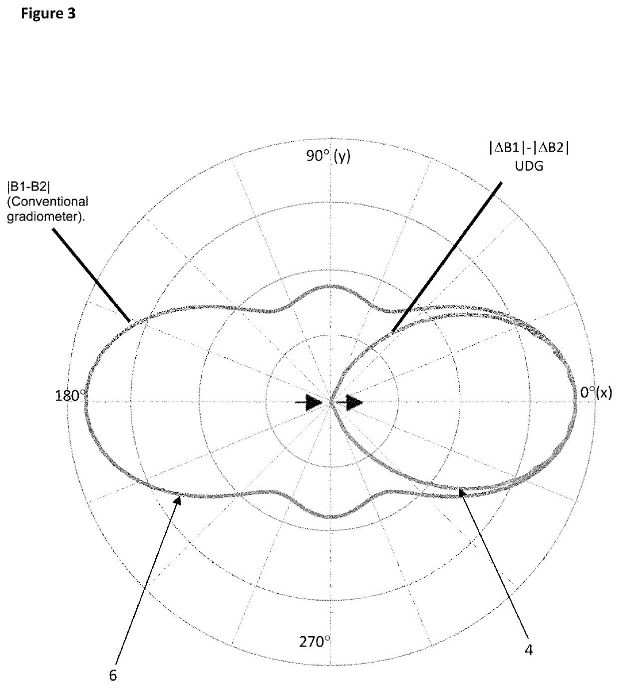
[0084]The two magnetic sensors S1, S2 are separated spatially by a small distance, typically up to 20 cm or 30 cm or thereabouts along a baseline, both typically being located within a common housing (not shown). Each magnetic sensor S1, S2, being omnidirectional, will define a ellipsoidal zone of detection with the magnetic sensor S1, S2 at the centre of the ellipsoid. Because of the small offset along the baseline relative to the diameter of t...


PUM


Abstract

An apparatus for detecting a moving ferromagnetic target object in a protected area comprises a first magnetic sensor adapted to measure a magnetic field within a first localised volume of space defined by a first zone of sensitivity of the first magnetic sensor and to produce a corresponding first measurement signal, and a second magnetic sensor adapted to measure a magnetic field within a second localised volume of space defined by a second zone of sensitivity of the second magnetic sensor and to produce a corresponding second measurement signal. The two magnetic sensors are separated spatially by a baseline such that the overlap between the two zones of sensitivity defines both a protected zone and a non-protected zone. A signal processing circuit is arranged in communication with the two magnetic sensors and is configured to process each of the first and second measurements signals to produce a respective first intermediate signal and a second intermediate signal which are each independent of the value of any non-changing background magnetic field that may be present in each zone of sensitivity, the value of the first and second intermediate signals thereby being dependent on the magnetic field associated with a target object moving in each zone of sensitivity. The first and second intermediate signals are proportional to the absolute change in magnetic field generated by the movement of the target object. The signal processing circuit also processes the two intermediate signals to provide an output signal that has a value that is indicative of whether the target object that caused the magnetic field is in the protected zone or in the non-protected zone.

Description

RELATED APPLICATIONS[0001]This application is a national phase application filed under 35 USC § 371 of PCT Application No. PCT / GB2018 / 052309 with an International filing date of Aug. 14, 2018, which claims priority of GB Patent Application 1713014.7 filed Aug. 14, 2017. Each of these applications is herein incorporated by reference in its entirety for all purposes.FIELD OF THE INVENTION[0002]This invention relates to an apparatus for use in protecting a protected area such as a doorway to a room that includes or leads to a magnetic resonance imagining (MRI) scanner. It in particular relates to the field of gradiometers and similar apparatus.BACKGROUND OF THE INVENTION[0003]Gradiometers have a wide range of applications but it is envisaged that the gradiometer of the invention may, in particular, be used for detecting the presence of ferromagnetic objects passing through a protected area such as the opening of a doorway into a room leading to a magnetic resonance imagining (MRI) scan...

Claims


Application Information

Patent Timeline
IPC IPC(8): G06F11/30G01V3/38G01R33/00G01V3/08
CPCG01V3/38G01R33/0005G01V3/08G01R33/0029
Inventor KEENE, MARKMANNING, PAUL A.
Owner METRASENS
Learn More