
Measuring shunt

Active Publication Date: 2022-07-12
SIEMENS AG
View PDF9 Cites 0 Cited by
  • Summary
  • Abstract
  • Description
  • Claims
  • Application Information

AI Technical Summary

Benefits of technology

The patent describes a measuring shunt that can be used to measure the current in an electronic circuit arrangement with half-bridges connected in parallel. The shunt also allows for the decoupling of the half-bridges without additional components. The shunt has an inductance that acts as a filter to reduce voltage gradients and asymmetries at the output of the circuit. This results in an improved functionality of the measuring shunt. The technical effects of the patent include improved current measurement and improved decoupling of electronic switches in half-bridges.

Problems solved by technology

Inductances can be used to decouple the electronic switches, but for reasons of cost they are frequently dispensed with.

Method used


Image

  • Measuring shunt
  • Measuring shunt

Examples


Embodiment Construction

[0026]Parts which correspond to one another are provided with the same reference characters in the figures.

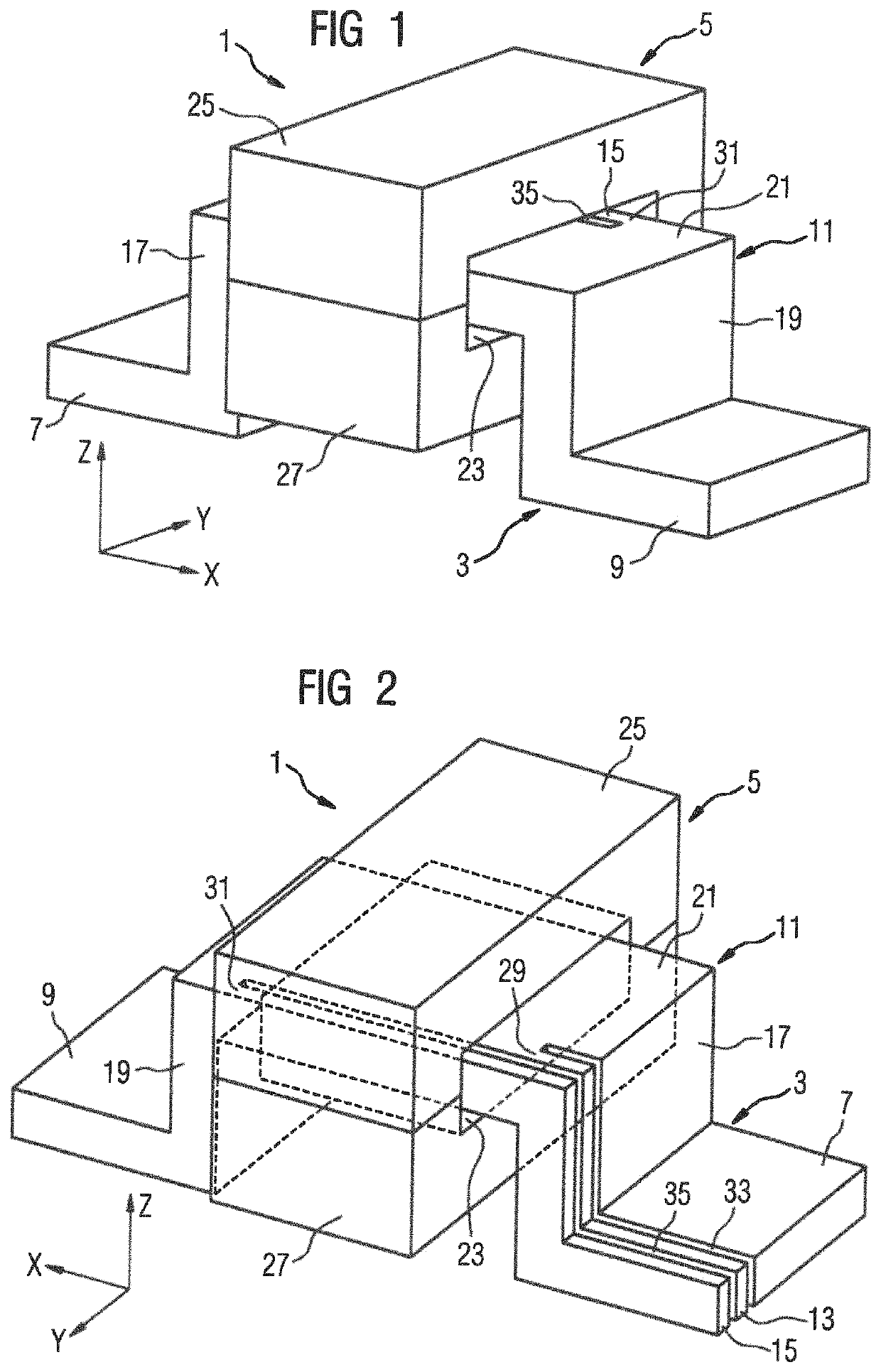
[0027]FIGS. 1 and 2 show two different perspective representations of an exemplary embodiment of a measuring shunt 1 according to the invention, wherein a Cartesian coordinate system with coordinates X, Y, Z is drawn to clarify the perspectives represented in each case. The measuring shunt 1 has a resistance element 3 and a magnetic core 5.

[0028]The resistance element 3 has two main contacts 7, 9, a middle section 11 and two auxiliary contacts 13, 15. The middle section 11 extends between the main contacts 7, 9. The middle section 11 is embodied as U-shaped with two limbs 17, 19 and a central section 21 extending between the limbs 17, 19. Each main contact 7, 9 is angled from one of the legs 17, 19, such that the main contacts 7, 9 protrude from the middle section 11 on opposing sides and directed away from one another.

[0029]The magnetic core 5 extends in an annular manner arou...


PUM


Abstract

A measuring shunt includes a resistance element and a magnetic core. The resistance element includes two main contacts and a middle section extending between the main contacts for conducting an electrical current between the two main contacts through the middle section. The magnetic core extends in an annular manner around the middle section of the resistance element.

Description

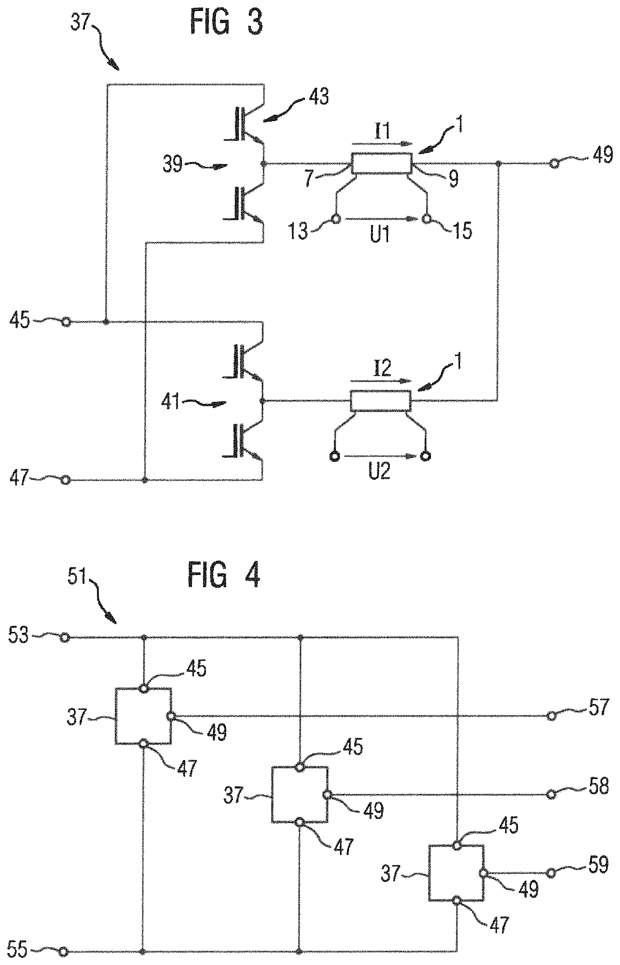
CROSS-REFERENCES TO RELATED APPLICATIONS[0001]This application is the U.S. National Stage of International Application No, PCT / EP2019 / 082391, filed Nov. 25, 2019, which designated the United States and has been published as International Publication No. WO 2020 / 114818 and which claims the priority of European Patent Application, Serial No. 18211063.5, filed Dec. 7, 2018, pursuant to 35 U.S.C. 119(a)-(d).BACKGROUND OF THE INVENTION[0002]The invention relates to a measuring shunt, in particular for circuit arrangements with parallel-connected half-bridges of electronic switches and power converters with circuit arrangements of this type.[0003]Parallel connections of half-bridges of electronic switches are used in particular in power converters to achieve a satisfactory power converter performance. In parallel connections of this type, electronic switches are arranged spatially closely adjacent, as a result of which the electronic switches are coupled. Inductances can be used to decoup...

Claims


Application Information

Patent Timeline
Patent Type & Authority Patents(United States)
IPC IPC(8): G01R15/14H02M1/00G01R1/20G01R17/10
CPCG01R15/146G01R1/203G01R17/10H02M1/0009H02M3/1588H01F17/06Y02B70/10
Inventor LORZ, ROLAND
Owner SIEMENS AG
Learn More