Human powered hydrofoil vehicle and use method

a technology of hydrofoil vehicle and hull, which is applied in the direction of marine propulsion, special-purpose vessels, vessel construction, etc., can solve the problems of large hulls, increased hull weight, and increased hull weight,

Active Publication Date: 2022-07-26
BRIGHT SPARK INNOVATIONS GP LTD
View PDF3 Cites 0 Cited by
  • Summary
  • Abstract
  • Description
  • Claims
  • Application Information

AI Technical Summary

Problems solved by technology

However, when the vehicle is in motion at a sufficient speed, the foils generate lift—and the bulk, if not all of the hull of the vehicle, will rise out of the water as it moves.
However, human powered hydrofoil vehicles that have hulls can require considerable effort to drive the vehicle at a speed sufficient to generate enough lift for it to be raised at least partially out of the water.
Furthermore, because a hull needs to be large enough to keep the combined static weight of the vessel and rider afloat, the consequential bulk brings along with it performance penalties when in motion.
Larger hulls introduce heavier payloads, transport/storage constraints, and higher production costs.
Therefore hydrofoil bikes with hulls have a number of design issues which limit their appeal.
The second group of human powered hydrofoil vehicles are those that lack buoyancy, and which will sink if insufficient lift is generated by its foils.
This operational transformation from ‘boat to plane’ poses certain disadvantages especially for pedal-powered hydrofoil craft, due to the limitations of human energy.
Thus users need to be relatively fit individua

Method used


Image

  • Human powered hydrofoil vehicle and use method
  • Human powered hydrofoil vehicle and use method
  • Human powered hydrofoil vehicle and use method

Examples


Embodiment Construction

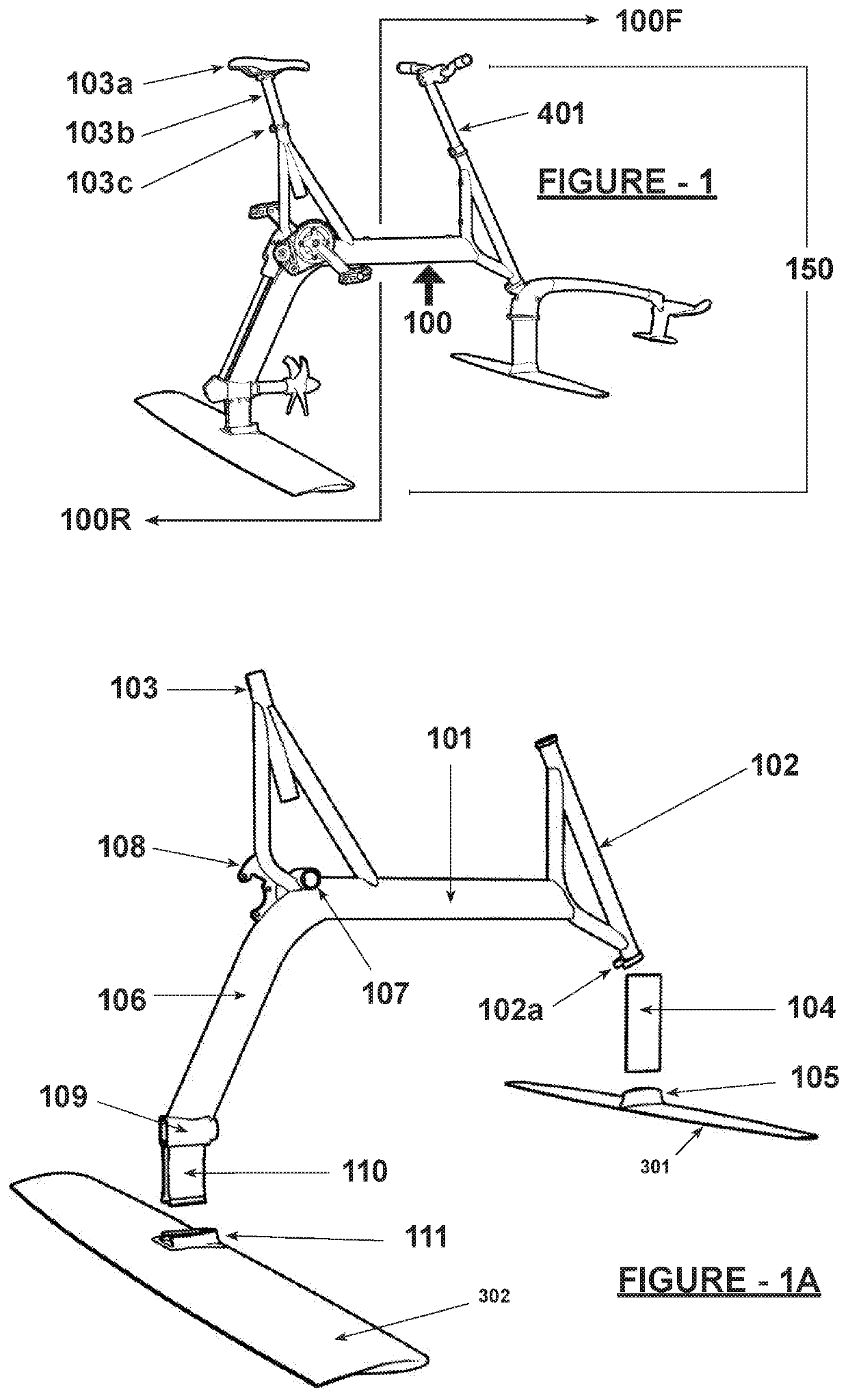
[0246]FIG. 1 depicts an exemplary embodiment of a hydrofoil bike (150) whereby all of its various assemblies and components are attached to its main frame (100). Generally the hydrofoil bike is subdivided into two sections—the front section (100F) wherein the steering and pitch / elevation of the vehicle is controlled; and the rear section (100R) from which the vehicle derives its mode of propulsion and its substantial source of lift.

[0247]The various parts of a preferred embodiment of the main frame (100) are depicted in FIGS. 1 and 1A. A horizontal member (101) of the main frame (100) connects the front section (100F) and the rear section (100R) together. The steering fork (401) (also seen in FIG. 4A) derives its orientation from the head tube (102) which also restricts the side to side movement of the fork (401) via a restrictor slot (102a).

[0248]A typical bike saddle (103a) is conventionally attached to a typical seat post (103b) which is then inserted into the seat tube (103) tha...


PUM


Abstract

The human powered hydrofoil bicycle includes multiple subsystems integrated together including a structural frame subsystem with associated steering and tiller module, a hydrofoil subsystem to provide vehicle lift, and a powertrain subsystem. The structural frame subsystem may be fitted with buoyancy modules to provide the overall vehicle with a near neutrally buoyant character. The structural frame subsystem also supports a seat for an operator and provides structural support for the steering and tiller module for the hydrofoil subsystem and the drivetrain subsystem. The hydrofoil subsystem includes multiple hydrofoil elements at lowermost portions of the vehicle. These hydrofoil elements generally include in a preferred embodiment a larger rear foil and a smaller front foil. The powertrain subsystem generally includes pedals rotatably supported on the vehicle at a convenient location for engagement and driving by feet of an operator. Power transmission elements extend from the pedals down to a prime mover such as a propeller.

Description

TECHNICAL FIELD[0001]The present invention relates to a device for use for transport over water and a method for using same. The invention has particular application to hydrofoil bikes, although it could be applied to other vehicles as appropriate.BACKGROUND ART[0002]Hydrofoil vehicles are those which are provided with hydrodynamic foils (which, for ease of reference, will now be referred to as foils) in a manner similar to aerofoils, such as those found on fixed-wing aircraft.[0003]A foil is a wing-like structure which is suspended transversely and horizontal under the hull of the vehicle (usually a boat such as a racing yacht or speedboat) and beneath the water surface. Typically, a hydrofoil vehicle will have at least two foils.[0004]When stationary, the hull of the hydrofoil vehicle rests on the water. However, when the vehicle is in motion at a sufficient speed, the foils generate lift—and the bulk, if not all of the hull of the vehicle, will rise out of the water as it moves. ...

Claims


Application Information

Patent Timeline
IPC IPC(8): B63B34/40B63B34/50B63B1/24B63B1/26B63H1/14B63H16/20B63H23/34B63H16/00
CPCB63B34/40B63B1/246B63B1/248B63B1/26B63B34/50B63H1/14B63H16/20B63H23/34B63H2016/005B63H2016/202B63H16/14
Inventor HOWARD-WILLIS, GUYCRUZ ALONZO, ROLANDO
Owner BRIGHT SPARK INNOVATIONS GP LTD
Why Eureka
Try Eureka