Conveyance device, driven unit, auxiliary unit, and pallet

a technology of conveying device and pallet, which is applied in the direction of mechanical conveyors, packaging, metal working devices, etc., can solve the problems of cost increase and cost increase, and achieve the effect of suppressing the manufacturing cost of pall

Active Publication Date: 2022-07-26
HIRATA & CO LTD
View PDF16 Cites 0 Cited by
  • Summary
  • Abstract
  • Description
  • Claims
  • Application Information

AI Technical Summary

Benefits of technology

[0005]It is an object of the present invention to provide a technique advantageous in changing specifications of a conveyance device and suppressing the manufacturing cost of a pallet.

Problems solved by technology

However, manufacturing a pallet from the beginning for each of different workpiece types and for each factory causes a cost increase.
Mounting a driving source such as a motor on a pallet causes a cost increase.

Method used


Image

  • Conveyance device, driven unit, auxiliary unit, and pallet
  • Conveyance device, driven unit, auxiliary unit, and pallet
  • Conveyance device, driven unit, auxiliary unit, and pallet

Examples


first embodiment

[0027]

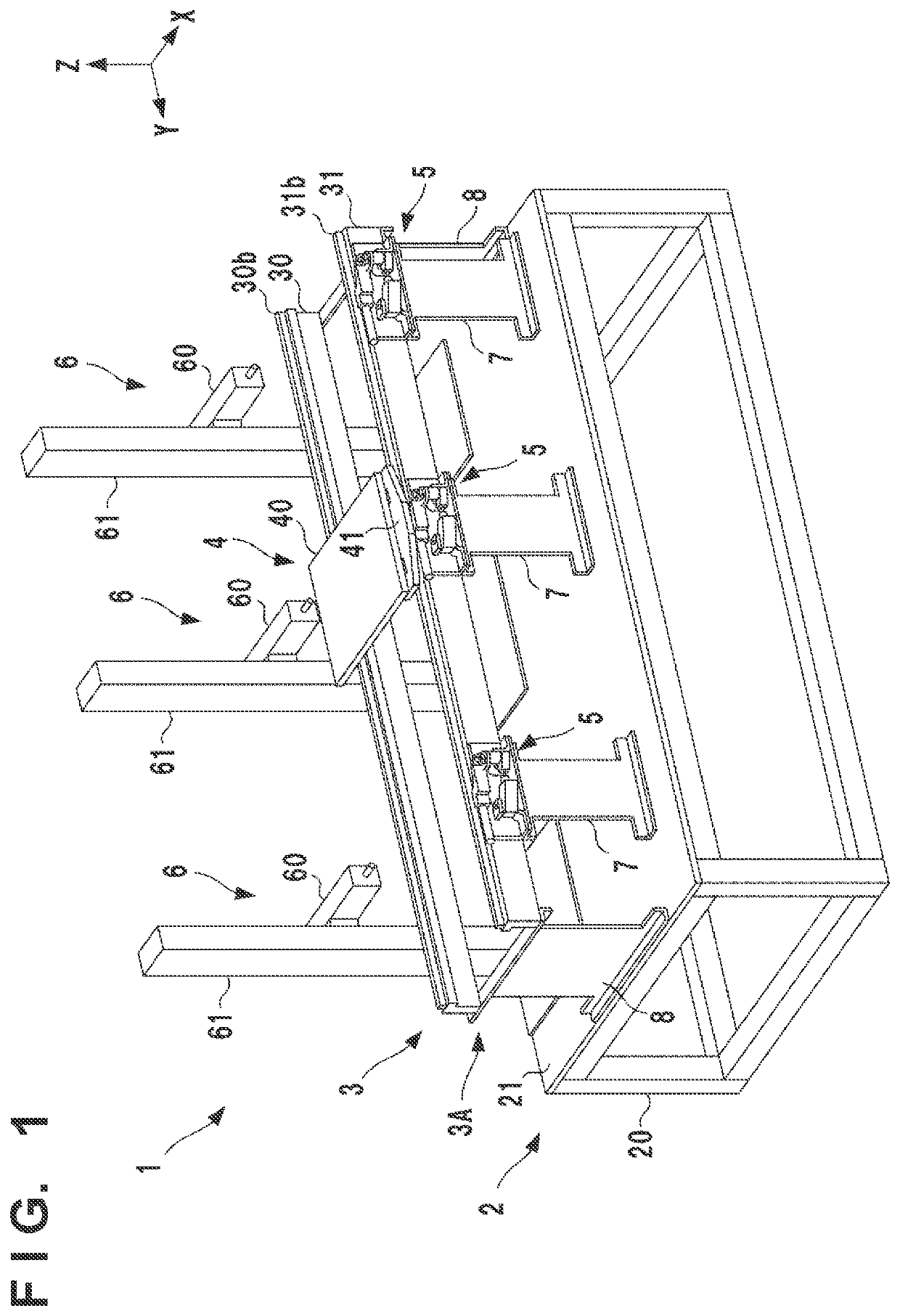
[0028]FIG. 1 is a perspective view of a work system 1 to which the present invention is applied. The work system 1 includes a stand 2, a conveyance device 3 that conveys a workpiece (not shown), and a plurality of work devices 6. The conveyance device 3 includes a plurality of stopping units 5. In an actual factory or the like, the work system is constructed by forming a conveyance layout using a plurality of the conveyance devices 3 based on the workpiece conveyance specifications, and appropriately arranging each work device 6 at a predetermined position in the formed conveyance layout. For example, as in a layout example shown in FIG. 18, a configuration can be constructed in which a plurality of the stands 2 and the conveyance devices 3 shown in FIG. 1 (two stands and two conveyance devices in the example shown in FIG. 18) are arranged in the Y direction.

[0029]The stand 2 is a structure that supports the conveyance device 3 and the plurality of work devices 6. The stand 2 ...

second embodiment

[0095]Detecting that the pallet 4 has reached the stop position can provide a guide for a timing of starting work on a workpiece by the work device 6. Therefore, a sensor for detecting that the pallet 4 has reached the stop position may be provided. In this case as well, by arranging a sensor on the support frame 31 and providing the driven unit 41 with a detection target portion to be detected by the sensor, alignment and the like upon changing specifications become easy.

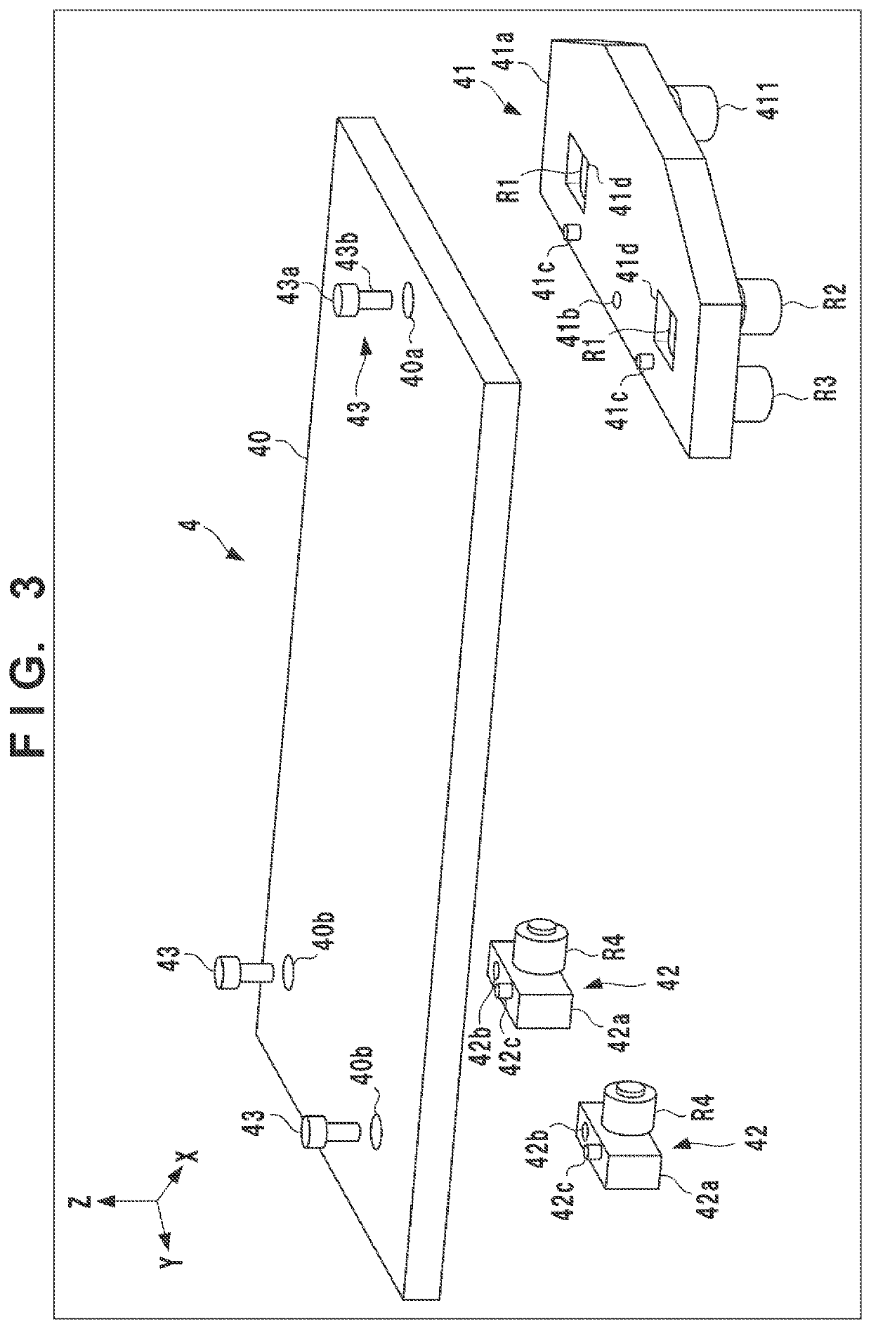
[0096]FIG. 15 is a perspective view showing an example of a driven unit 41 provided with a detection target portion 412. In the example shown in FIG. 15, the detection target portion 412 is fixed to the inner side surface of a main body member 41a. FIG. 16 is a sectional view showing an arrangement example of a sensor 9 that detects the detection target portion 412. The sensor 9 is, for example, an optical sensor or a magnetic sensor, and detects whether the detection target portion 412 exists immediately above it....

third embodiment

[0098]The numbers and positions of the driven units 41 and the auxiliary units 42 in the pallet 4 can be appropriately selected. FIG. 17 shows another arrangement example of the pallet 4. The shown example is an arrangement example of a pallet 4 suitable for a relatively large workpiece. Six auxiliary units 42 are provided. Two of them are arranged at the front and back of a driven unit 41 and configured to travel on the support frame 31 (not shown in FIG. 17). Remaining four auxiliary units 42 are configured to travel on the support frame 30 (not shown in FIG. 17). When it is necessary to change the specifications of the pallet 4 since the type of workpiece is changed, it is possible to change the specifications as described above. In this case as well, it is not required to redesign the driven unit 41 and the auxiliary unit 42, and only a placement member 40 may be newly designed.


PUM


Abstract

A conveyance device includes a pair of first and second support frames provided so as to be parallel to each other, and configured to define a conveyance track of a pallet; a driving unit provided on the first support frame and configured to apply a conveyance force to the pallet; a driven unit as a unit forming the pallet, configured to travel along a first guide portion of the first support frame by the driving unit; an auxiliary unit as a unit forming the pallet, connected to the driven unit via a placement member of the pallet and capable of freely traveling along a second guide portion of the second support frame, and a stopping unit including an engaging portion that engages with a portion of the driven unit, and configured to temporarily stop a movement of the pallet.

Description

CROSS-REFERENCE TO RELATED APPLICATION[0001]This application is a Continuation of International Patent Application No. PCT / JP2018 / 025592, filed Jul. 5, 2018, the entire disclosure of which is incorporated herein by reference.TECHNICAL FIELD[0002]The present invention relates to a workpiece conveyance technique using a pallet.BACKGROUND ART[0003]A system is known in which, when a workpiece is to be conveyed, the workpiece is placed on a pallet serving as a transfer body and the workpiece is conveyed by moving the pallet (for example, Japanese Patent Laid-Open No. 2005-28459). If some processing is performed on the workpiece during the conveyance, it is necessary to temporarily stop the workpiece. Japanese Utility Model Registration No. 2601873 discloses a system having such a temporary stop function. The pallet is basically a dedicated product for each workpiece. However, manufacturing a pallet from the beginning for each of different workpiece types and for each factory causes a cos...

Claims


Application Information

Patent Timeline
Patent Type & Authority Patents(United States)
IPC IPC(8): B65G35/06B23Q7/14B65G47/88B65G35/08
CPCB65G35/06B23Q7/1452B65G35/08B65G47/88B65G2201/0267B65G2203/0283B65G25/06B65G47/74B23Q7/003B65D19/42
Inventor YOKOYAMA, SHINJI
Owner HIRATA & CO LTD
Why Eureka
Try Eureka