
Bladeless fan and air outlet cylinder thereof

a bladeless fan and air outlet technology, applied in the field of bladeless fans and air outlet cylinders, can solve the problems of large space required, uneven ejection of air stream, and ineffective wind generated by the fan to achieve the effect of quick cooling for users

Active Publication Date: 2022-07-26
YING HUI
View PDF9 Cites 0 Cited by
  • Summary
  • Abstract
  • Description
  • Claims
  • Application Information

AI Technical Summary

Benefits of technology

The present invention provides a small bladeless fan with a novel and aesthetical design that increases wind power, effective wind distance, and reduces noise. The fan has longitudinally arranged air outlet slits that facilitate the air stream to be compressed and focused before ejecting outwardly. The air stream guiding opening and the air collection openings have a tapered guiding structure that multiplies the speed of the air stream, resulting in a higher volume of wind. The air outlet cylinder has a separable structure, and its internal passage is configured as a longitudinal passage, ensuring even distribution of the air stream and increasing the yield rate of the product.

Problems solved by technology

1. The basic air stream ejected out from the circular vent is dispersed and not focused. Therefore, when the fan is used distal from the user, the user can only experience the air stream ejected out from the circular vent having a slow speed and a small volume. As such, wind generated by the fan is not effective to achieve quick cooling purpose for the user.
2. The circular passage create a circular pathway for the basic air stream inside the air outlet portion, but this leads to uneven distribution of the air stream in the circular passage, and thus the uneven ejection of air stream.
3. Large space is required and is therefore disadvantageous to disposition, use, and storage etc.
4. The fan is noisy, especially when the fan is required to provide high speed air stream. The noise is particularly acute when the impeller of the fan cuts into the air when it rotates at a high speed. As such, the noise significantly affects the environment of use.

Method used


Image

  • Bladeless fan and air outlet cylinder thereof
  • Bladeless fan and air outlet cylinder thereof
  • Bladeless fan and air outlet cylinder thereof

Examples


Embodiment Construction

[0035]The present invention will be further described in detail below with reference to an embodiment as illustrated by the accompanying drawings.

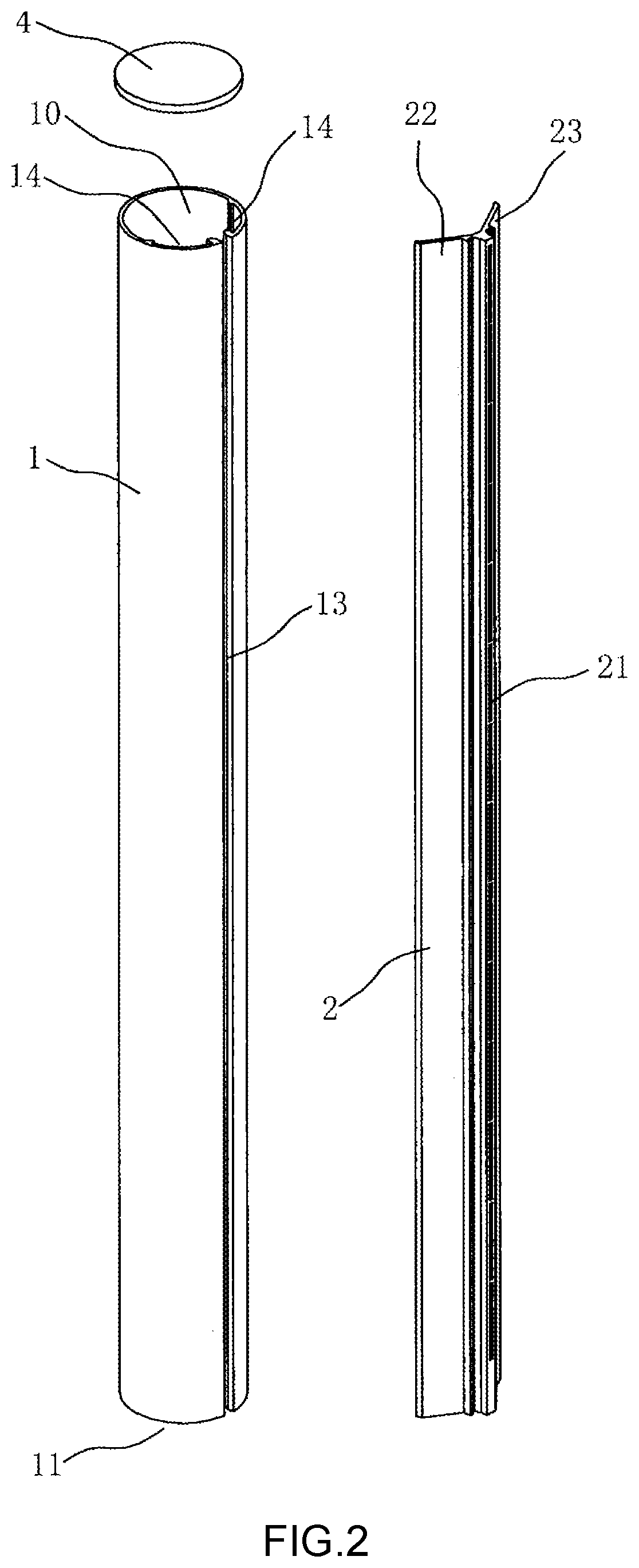
[0036]FIGS. 1-8 illustrate a preferred embodiment of an air outlet cylinder of a bladeless fan according to the present invention, comprising a cylinder 1 and a nozzle 2; the cylinder is provided with an air inlet 11 that receives air stream, and an internal passage 12; a front side wall of the cylinder 1 is provided with an opening 13 running longitudinally through an upper side and a lower side of the cylinder; a position limiting groove 14 also running longitudinally through the upper side and the lower side of the cylinder is provided on an inner wall surface of the cylinder inside the cylinder at each of two sides of the opening 13. The nozzle 2 comprises a mouth portion 21 inserted into the opening 13, and a first air stream guiding portion 22 and a second air stream guiding portion 23 each inserted into a corresponding position limi...


PUM


Abstract

An air outlet cylinder of a bladeless fan is provided, having an air cylinder and a nozzle; the air cylinder is provided with an air inlet for receiving airflows, and an internal channel; the front-end sidewall of the air cylinder is provided with an opening extending longitudinally therethrough; the inner wall surface at each of two sides of the opening in the air cylinder is separately provided with a limiting groove extending longitudinally therethrough; the nozzle has a mouth part embedded in the opening, and two airflow guiding parts respectively embedded in the corresponding limiting grooves; multiple air outlet slits are longitudinally spaced on the mouth part; airflows received in the internal channel are sprayed from the air outlet slits. A bladeless fan having the air outlet cylinder is also provided.

Description

BACKGROUND OF THE INVENTION[0001]The present invention relates to the technical field of fan, and more specifically relates to a bladeless fan and an air outlet cylinder thereof.[0002]Nowadays, an air outlet portion of a bladeless fan is usually circular in shape, comprising a circular passage for receiving a basic air stream and a circular vent for ejecting the basic air stream, and also comprising a circular opening that guides external air to a proximity of the circular vent to mix with the basic air stream ejected out from the circular vent. Such an air outlet portion is structurally defective during use in respect of the following aspects:[0003]1. The basic air stream ejected out from the circular vent is dispersed and not focused. Therefore, when the fan is used distal from the user, the user can only experience the air stream ejected out from the circular vent having a slow speed and a small volume. As such, wind generated by the fan is not effective to achieve quick cooling ...

Claims


Application Information

Patent Timeline
Patent Type & Authority Patents(United States)
IPC IPC(8): F04D25/08F04D29/42F04D29/44F04F5/16F04F5/46
CPCF04D25/08F04D29/4206F04D29/441F04F5/16F04F5/46F04F5/44F04F5/466F04D29/624F04D29/023F05D2210/12F05D2300/10F05D2300/43
Inventor YING, HUI
Owner YING HUI
Learn More