Sprocket

a technology of sprockets and sprockets, which is applied in the direction of driving chains, gearing, hoisting equipment, etc., can solve the problems of vibration and noise in the entire chain driving gear, and achieve the effects of reducing vibration and noise, reducing impact and striking sound, and improving durability

Active Publication Date: 2022-08-02
TSUBAKIMOTO CHAIN CO
View PDF7 Cites 0 Cited by
  • Summary
  • Abstract
  • Description
  • Claims
  • Application Information

AI Technical Summary

Benefits of technology

[0013]The present invention is made to solve the problems of the conventional art explained above. That is, an object of the present invention is to provide a sprocket that reduces an impact and striking sound due to contact and seating at engaging of the sprocket with a chain, reduces vibration and noise in the entire chain driving gear, and improves durability.
[0020]With the configuration according to another aspect of the invention, the interference amount at the time of seating between the first convex sections and the inner link plates of the chain is equal to the interference amount at the time of seating between the second convex sections and the outer link plates of the chain. With this configuration, even when the heights of the inner link plates and the outer link plates are different, it is possible to equalize reaction forces applied from the cushion ring to the link plates and to suppress vibration due to a difference in reaction forces between the inner link plates and the outer link plates.

Problems solved by technology

Although the impact and the striking sound due to the contact and the seating at engagement of the cushion ring with the chain decrease, vibration, resonance, and the like of the chain are caused because two types of reaction forces alternately appear at an equal interval, which may cause vibration and noise in the entire chain driving gear.

Method used


Image

  • Sprocket
  • Sprocket

Examples


embodiment 1

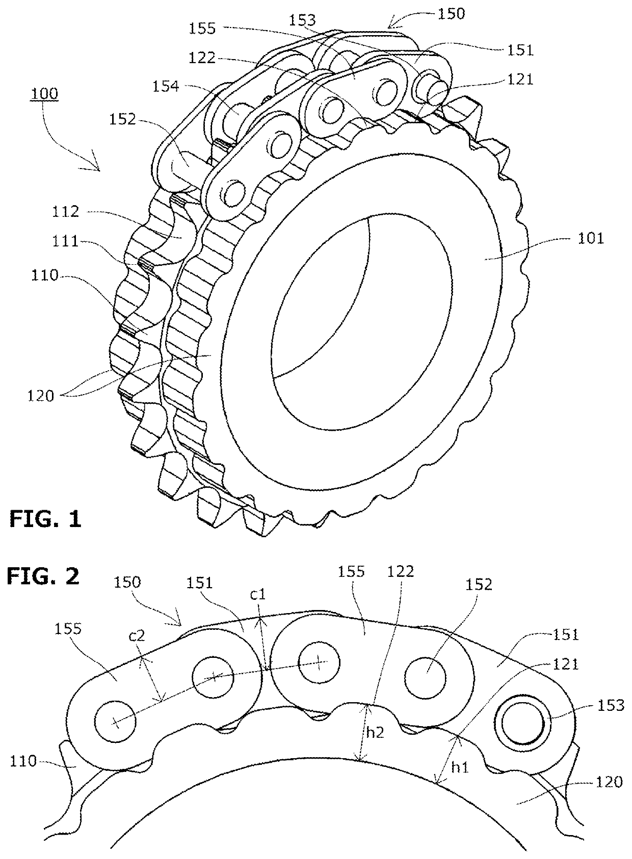
[0029]A sprocket 100 according to a first embodiment of the present invention includes, as shown in FIGS. 1 and 2, a sprocket main body 101, on the circumferential surface of which a plurality of teeth 110 including tooth tips 111 and teeth bottoms 112 are formed, and cushion rings 120 that is made of an elastic member and is provided on both side surfaces of the sprocket main body 101. The outer circumferences of a cushion ring 120 comes into contact with the link plates of the chain.

[0030]First convex sections 121 and second convex sections 122 are alternately provided in the circumferential direction in the outer circumferences of the cushion rings 120 on both the side surfaces. They are formed so that the centers of the first convex sections 121 and the second convex sections 122 be located at corresponding positions to the tooth tips 111.

[0031]Herein, the term “corresponding positions” in the circumferential direction refers to positions having identical angles in the circumfer...

embodiment 2

[0038]A sprocket according to a second embodiment of the present invention has the same configuration as the sprocket according to the first embodiment except that the cushion ring 120B is installed.

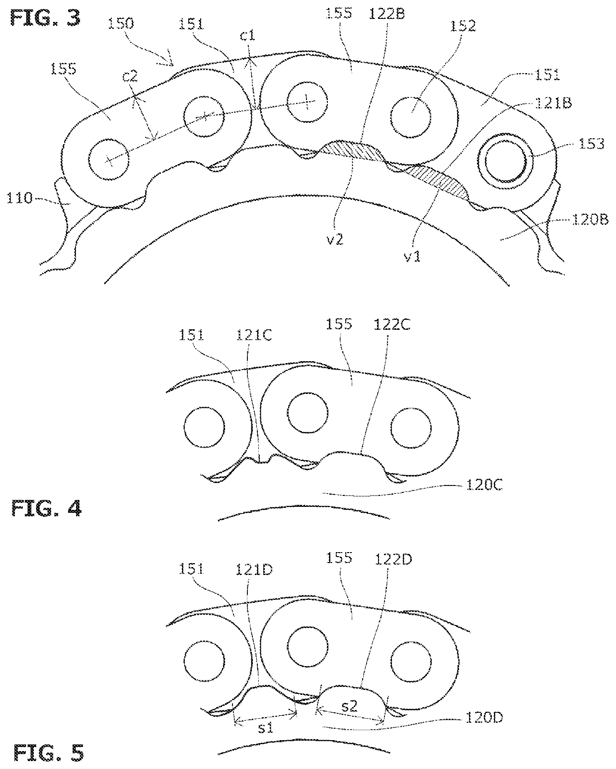
[0039]The cushion ring 120B of the sprocket according to the second embodiment is formed such that, as shown in FIG. 3, an interference amount (volume) v1 between a first convex section 121B and the inner link plate 151 be equal to an interference amount (volume) v2 between a second convex section 122B and the outer link plate 155 at the time when the chain 150 is seated.

[0040]With this configuration, even when the heights of the inner link plate 151 and the outer link plate 155 are different, it is possible to equalize reaction forces applied from the cushion ring 120B to the link plates and to suppress vibration due to a difference in reaction forces between the inner link plate 151 and the outer link plate 155.

embodiment 3

[0041]As shown in FIG. 4, a sprocket according to a third embodiment of the present invention has the same configuration as the sprocket in the first or second embodiment except that the cushion ring 120C is installed.

[0042]The cushion ring 120C of the sprocket according to the third embodiment is formed such that the shape of a first convex section 121C to which the inner link plate 151 interferes be different from a shape of a second convex section 122C to which the outer link plate 155 interferes


PUM


Abstract

In a sprocket including a cushion ring coming into contact with link plates of a chain, the cushion ring includes, on an outer circumferential surface, a plurality of convex sections coming into contact with the link plates, and the plurality of convex sections are provided at corresponding positions to tooth tips at identical pitches to a plurality of teeth and include convex sections having different shapes.

Description

BACKGROUND OF THE INVENTION1. Field of the Invention[0001]The present invention relates to a sprocket. In the sprocket, a plurality of teeth engaging with pins, bushes, or rollers of a chain are formed on the circumferential surface of the main body of the sprocket. The sprocket includes a cushion ring on a side surface of the main body, and the outer circumferential surface of the cushion ring is configured to come into contact with link plates of the chain.2. Description of the Related Art[0002]A chain driving gear that suspends a chain on at least two sprockets on a driving side and a driven side and transmits power has been widely used. In any use of the chain driving gear, it is desirable to reduce a noise level.[0003]In particular, striking sound due to contact of sprocket teeth with and seating of sprocket teeth on pins, bushes, or rollers caused at the start of engaging of the chain with the sprocket is a major factor of noise. Reduction of the noise is required for chain dr...

Claims


Application Information

Patent Timeline
Patent Type & Authority Patents(United States)
IPC IPC(8): F16H55/14F16H55/30F16H57/00
CPCF16H55/14F16H55/30F16H57/0006F16H2055/306F16H7/06F16G13/08
Inventor MORI, KAORIKUREMATSU, YUJI
Owner TSUBAKIMOTO CHAIN CO
Why Eureka
Try Eureka